Selectably engageable clutch for a device

a technology of selectable engagement and drive device, which is applied in the direction of clutches, mechanical control devices, instruments, etc., can solve the problems of placing stress on the user attempting to steer the device, physical movement is problematic, and the steering wheel-like mechanism cannot be used to facilitate orientation, so as to prevent undesirable axial movement of the clutch member

Inactive Publication Date: 2005-11-29
HUSQVARNA OUTDOOR PROD INC
View PDF16 Cites 34 Cited by
  • Summary
  • Abstract
  • Description
  • Claims
  • Application Information

AI Technical Summary

Benefits of technology

[0007]In accordance with another aspect, the present invention provides a clutch assembly comprising means for preventing undesirable axial movement of a clutch member to a position where the clutch member does not transfer rotational energy to a wheel drive member.

Problems solved by technology

Because these devices typically do not include articulated wheel-axle joints, there is no steering wheel-like mechanism to facilitate the orientation.
These devices contain many attributes that make such physical moving problematic.
For example, these devices can be very heavy, thus placing stress on the user attempting to steer the device.
Also, these devices are operated under conditions that make such physical moving difficult.
As the snow thrower progresses through the snow, manual movement is impeded by surrounding barriers of snow.

Method used


Image

  • Selectably engageable clutch for a device
  • Selectably engageable clutch for a device
  • Selectably engageable clutch for a device

Examples


Embodiment Construction

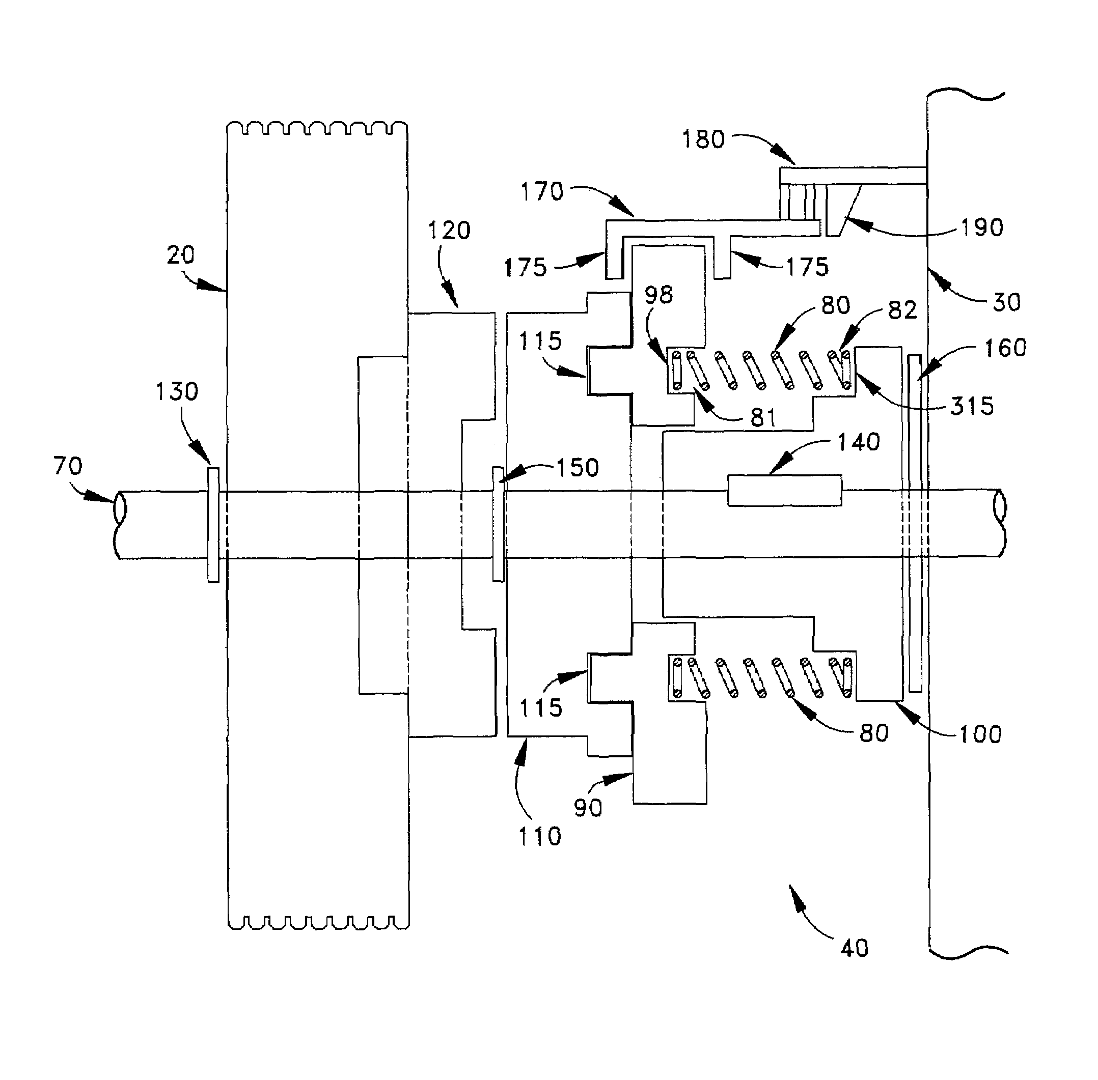
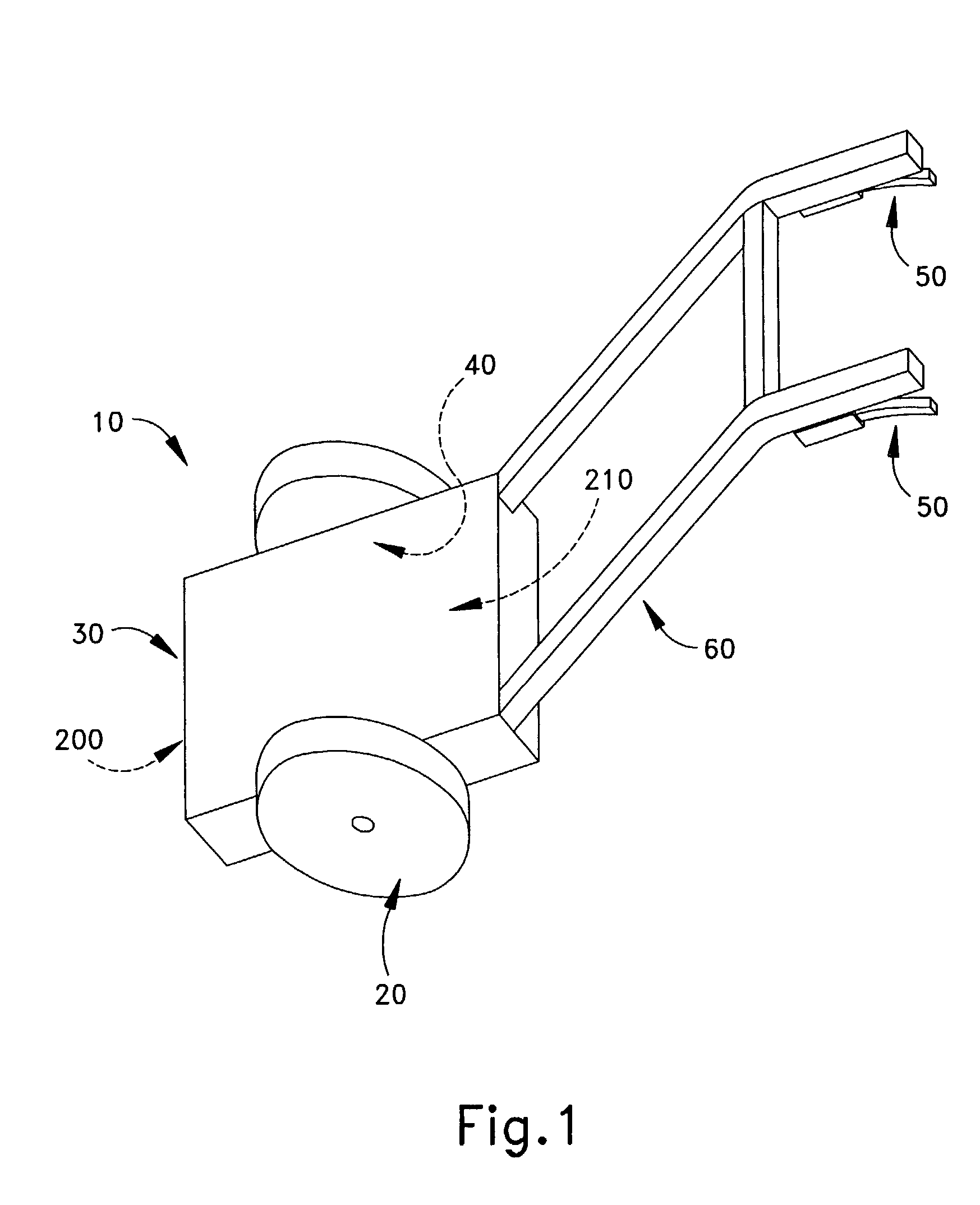
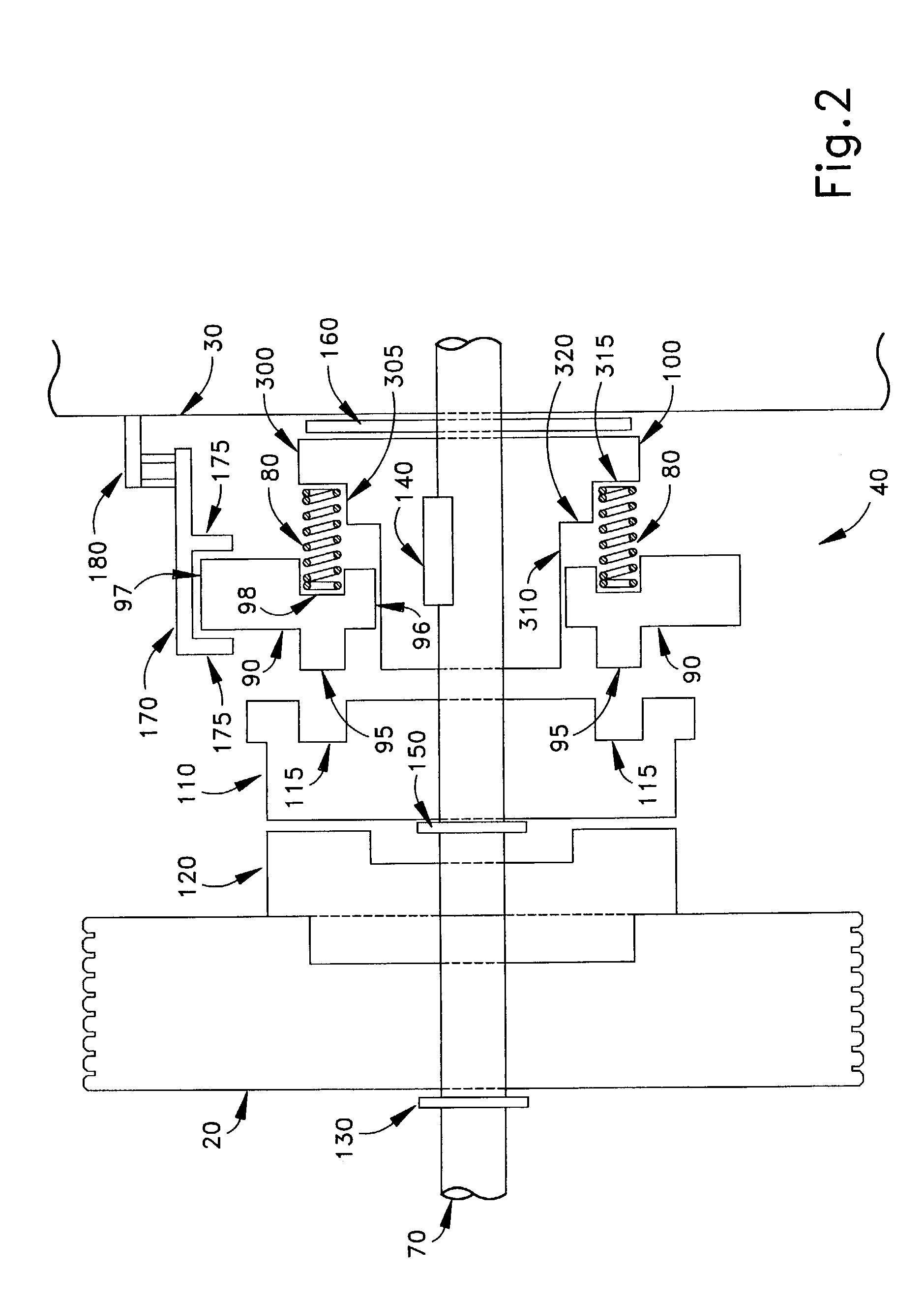
[0013]In accordance with an example embodiment, the present invention provides a selectably engageable clutch assembly 40 (FIG. 2) and a device 10 (schematically shown in FIG. 1) having the selectably engageable clutch assembly 40 utilized therein. The device 10 (FIG. 1) according to the present invention may be any device having one or more wheels and may include structure for performing a desired function. Such a device 10 may be a grass cutter, snow thrower, etc., and FIG. 1 shown structure of the device in only the most basic schematic form. It is to be understood that these devices are for example only and that the clutch 40 is applicable to other types of devices.

[0014]With reference to FIG. 1, the device 10 includes a housing 30, one or more wheels 20, and handle bars 60. The housing 30 generally includes operative elements, such as an environmental interface 200, a drive source 210 and drive elements. The environmental interface 200 performs the desired functions of the devi...


PUM


Abstract

A clutch assembly selectively transfers rotational energy from a rotatable drive shaft to a wheel. The clutch assembly includes a drive transmitting member rotationally coupled to the drive shaft, a clutch member rotationally coupled to the drive transmitting member and movable relative to the drive transmitting member, and a wheel drive member adapted to receive a rotational energy from the clutch member. In one aspect, the clutch assembly is for selectively transmitting drive force from a rotational drive source to a single wheel of a multi-wheeled power driven device. The clutch assembly includes a member axially movable relative to the rotational drive source to transmit rotational energy toward the wheel when the member is in one axial position.

Description

FIELD OF THE INVENTION[0001]The present invention relates to clutches, and more particularly the present invention relates to a selectably engageable clutch for a driven device.BRIEF DISCUSSION OF THE RELATED ART[0002]Cutting grass and blowing snow, for example, are activities facilitated by the use of certain self-powered devices, such as grass cutters and snow blowers. These devices typically include one or more wheels and may include a drive source for providing a propulsive force to the wheels, thus reducing the need for a user to push the device. To use the device, a user must actuate the necessary components of the device and orient the same along a desired direction. This orientation generally involves the user manually turning the device. Because these devices typically do not include articulated wheel-axle joints, there is no steering wheel-like mechanism to facilitate the orientation. Thus, the entire device must physically be moved or turned.[0003]These devices contain ma...

Claims


Application Information

Patent Timeline
Patent Type & Authority Patents(United States)
IPC IPC(8): F16D11/08F16D11/14F16D23/12
CPCF16D11/08F16D11/14F16D23/12
Inventor BUCKHOUSE, NORMANSCOTT, MICHAEL
Owner HUSQVARNA OUTDOOR PROD INC
Why Eureka
Try Eureka