Bulk container with plastic liner

a technology of plastic liner and container, which is applied in the field of container, can solve the problems of reducing the quantity of retained material in the container, incomplete discharge of liner contents, and increasing the cost of the container, and achieves the effect of effective height of the liner within the sleev

Inactive Publication Date: 2005-11-29
SHUERT LYLE H
View PDF15 Cites 121 Cited by
  • Summary
  • Abstract
  • Description
  • Claims
  • Application Information

AI Technical Summary

Benefits of technology

[0006]According to the invention, the liner includes an upper portion of uniform cross-sectional configuration conforming to the cross-sectional configuration of the sleeve and a lower portion of downwardly and inwardly tapering configuration terminating at a bottom liner opening positioned proximate the pallet discharge port. This arrangement facilitates the substantially total discharge of the contents of the container.
[0007]According to a further feature of the invention, the effective height of the liner within the sleeve with the upper edge of the upper liner portion secured to the upper edge of the sleeve is greater than the distance from the upper edge of the sleeve to the top face of the pallet proximate of ...

Problems solved by technology

Whereas this type of container is generally satisfactory, the discharge of the liner contents is incomplete since large quantities of bulk material remain in the liner in the annular area surrounding the discharge ...

Method used


Image

  • Bulk container with plastic liner
  • Bulk container with plastic liner
  • Bulk container with plastic liner

Examples


Embodiment Construction

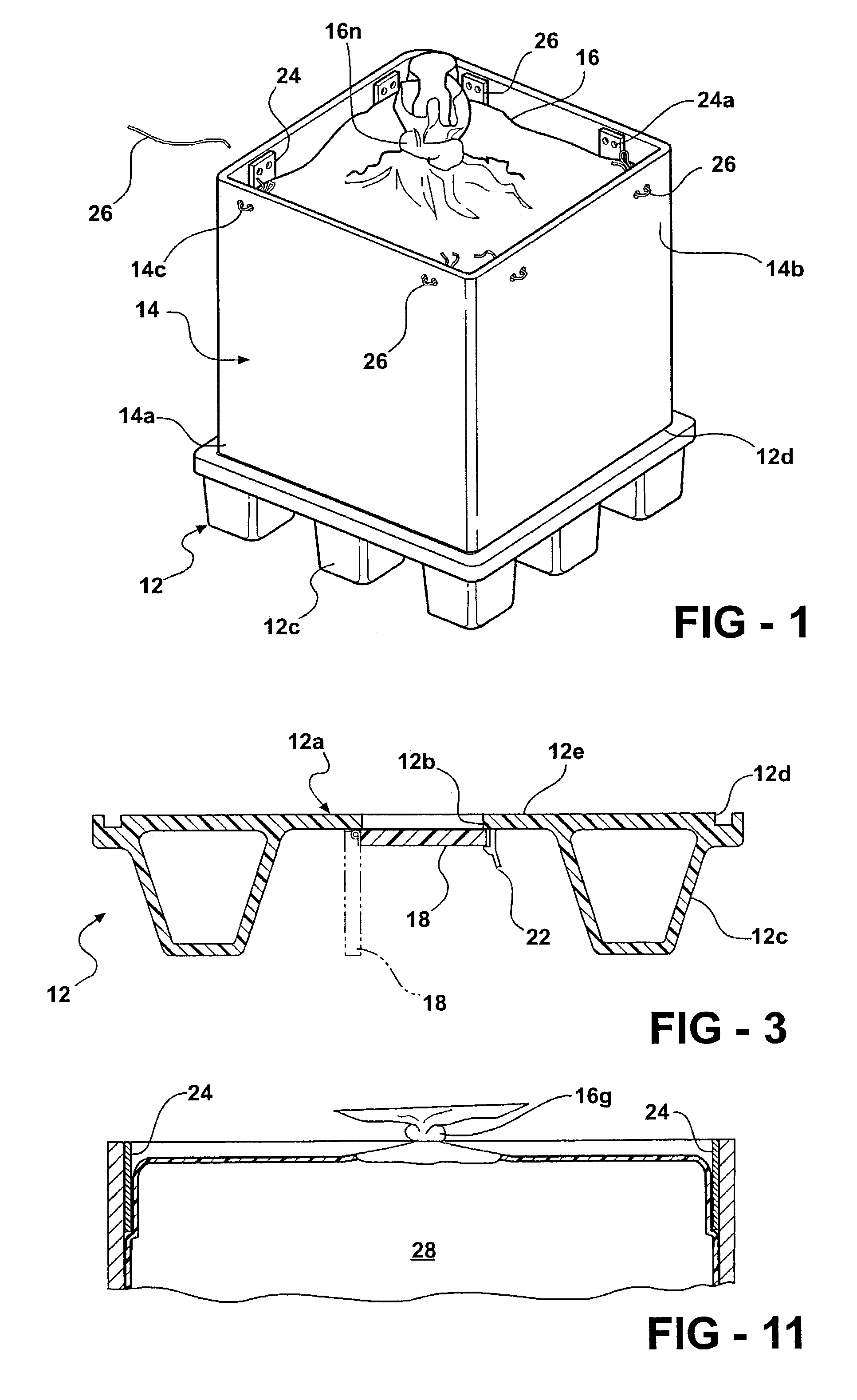
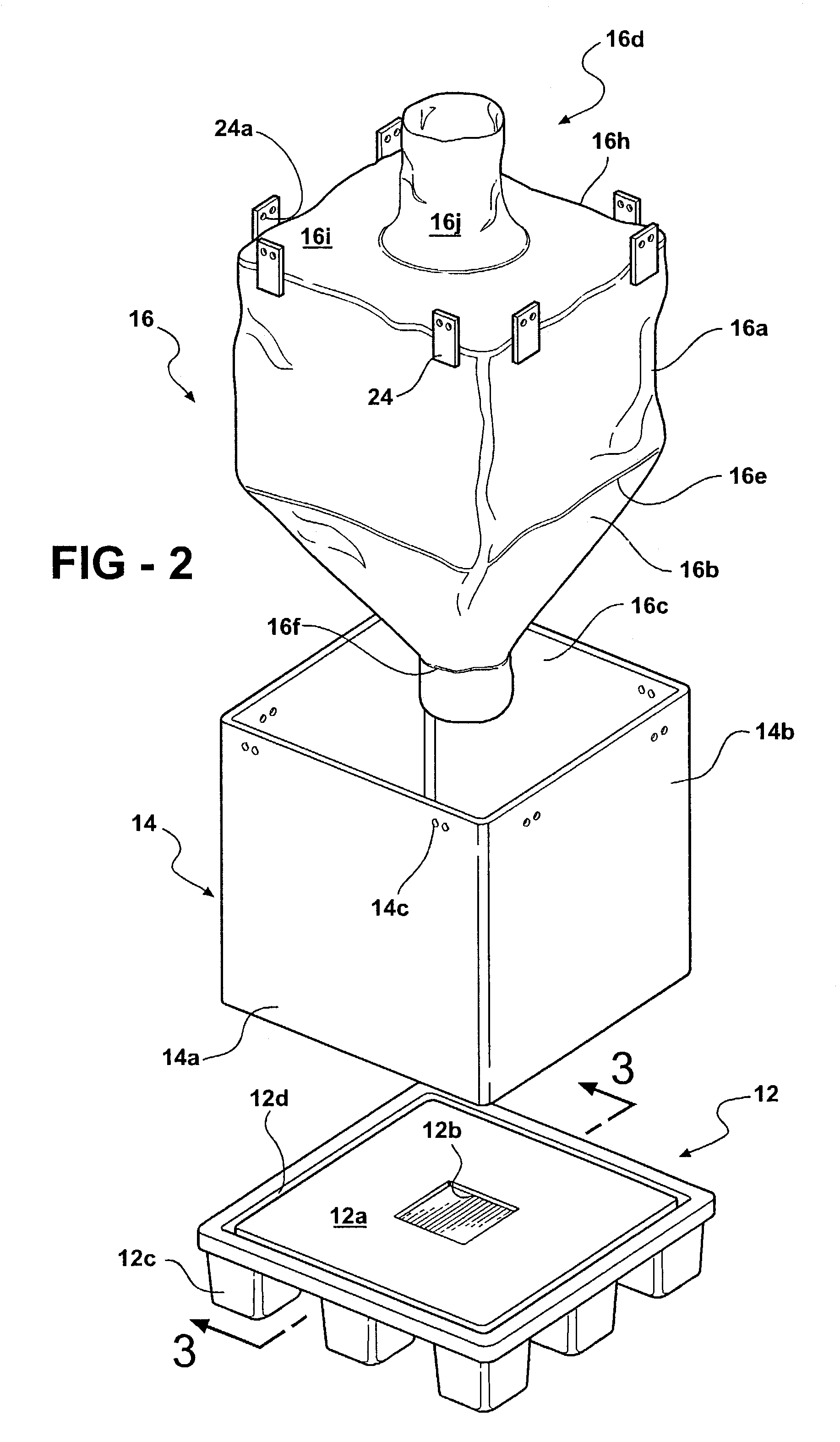
[0017]The container 10 seen in FIG. 1, broadly considered, includes a rigid plastic pallet 12, a sleeve 14, and a liner 16.

[0018]Pallet 12 has a rectangular configuration and is formed in a molding operation of a rigid plastic material such, for example, as polyethylene. Pallet 12 may be vacuum formed in a twin sheet operation or may, as shown for simplicity, have a single sheet construction. Pallet 12 includes a central platform portion 12a defining a central rectangular discharge port 12b, and a plurality of down-standing legs 12c operative to maintain the platform portion 12a in spaced relation to a support surface. An annular upwardly opening rectangular groove 12d is defined around the periphery of the platform portion and a trap door 18 is pivotably mounted at pivot point 20 to the under face of the platform portion of the pallet. Trap door 18 is moveable pivotably about pivot point 20 between a closed position seen in solid lines in FIG. 3, in which the port 12b is closed, an...


PUM


Abstract

A container including a rigid plastic pallet having a platform portion defining a central discharge port, a tubular cardboard sleeve supported at a lower edge thereof on the pallet, and a flexible plastic liner positioned within the sleeve. The liner includes an upper portion of uniform cross-sectional configuration conforming to the cross-sectional configuration of the sleeve and a lower portion of downwardly and inwardly tapering configuration terminating in a bottom liner opening positioned proximate the pallet discharge port. The effective combined height of the upper and lower portions of the liner, with the upper edge of the upper liner portion secured to the upper edge of the sleeve, is greater than the distance from the upper edge of the sleeve to the upper face of the pallet so that the sides of the lower portion may bulge outwardly in response to the loading of contents into the liner to at least partially fill the annular void defined between the sleeve and the lower portion of the liner with the liner fully extended. The pallet port is selectively closed by a trap door pivotedly mounted on the pallet. The pallet port is selectively closed by a trap door pivotally mounted on the pallet and the liner includes a discharge spout extending downwardly from the lower portion of the liner for passage through the pallet discharge port.

Description

BACKGROUND OF THE INVENTION[0001]This invention relates to containers and more particularly to containers that are especially suitable for use with bulk materials.[0002]Bulk containers are known wherein the container includes a rigid plastic pallet having a platform portion defining a central discharge port, a tubular sleeve supported in upstanding fashion on the upper face of the pallet, and a flexible plastic liner positioned within the sleeve and including a bottom opening so that bulk material contained within the liner may be selectively discharged from the container by opening the bottom of the liner and discharging the liner contents downwardly through the discharge port in the pallet. Whereas this type of container is generally satisfactory, the discharge of the liner contents is incomplete since large quantities of bulk material remain in the liner in the annular area surrounding the discharge port. In an effort to overcome this problem of retained bulk material, it has bee...

Claims


Application Information

Patent Timeline
IPC IPC(8): B65D19/00B65D19/20B65D77/06
CPCB65D19/0028B65D19/20B65D77/061B65D2519/00034B65D2519/00069B65D2519/00159B65D2519/00268B65D2519/00288B65D2519/00338B65D2519/00497B65D2519/00621B65D2519/00641B65D2519/00805
Inventor SHUERT, LYLE H.
Owner SHUERT LYLE H
Why Eureka
Try Eureka