Two-way caster bench

a caster bench and two-way technology, applied in the field of two-way caster benches, can solve the problems of increasing production costs and wasting available workspa

Inactive Publication Date: 2005-11-29
SHINN FU
View PDF12 Cites 46 Cited by
  • Summary
  • Abstract
  • Description
  • Claims
  • Application Information

AI Technical Summary

Benefits of technology

[0007]It is a further objective of the present invention to provide a locating device mounted on one of the pivoting points between the rear chair frame and the middle chair frame for locking the middle chair frame in its folded configuration, the device being defined by the middle chair frame being supported by the supporting bar of the rear chair frame. The locating device assures the safety of the two-way caster bench.

Problems solved by technology

Since the conventional work-related chairs are either a lying bench or a stepping chair, a work place sometimes has to be provided with these two types of chairs, which waste available workspace and increase production cost.

Method used


Image

  • Two-way caster bench
  • Two-way caster bench
  • Two-way caster bench

Examples


Embodiment Construction

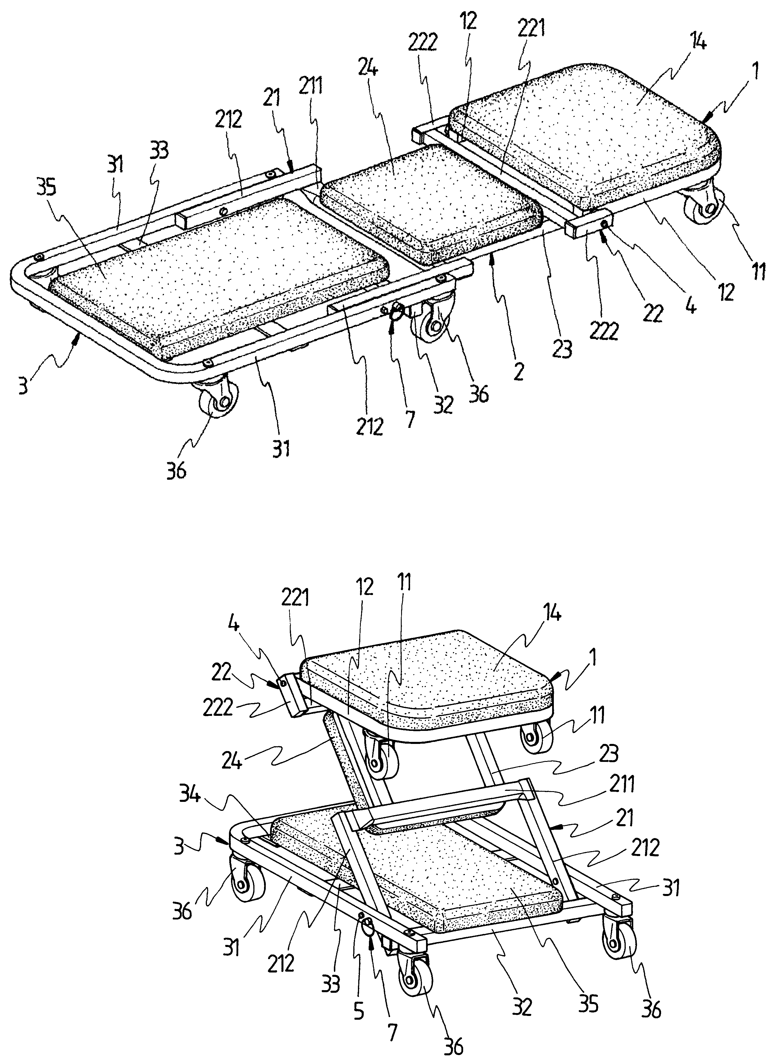
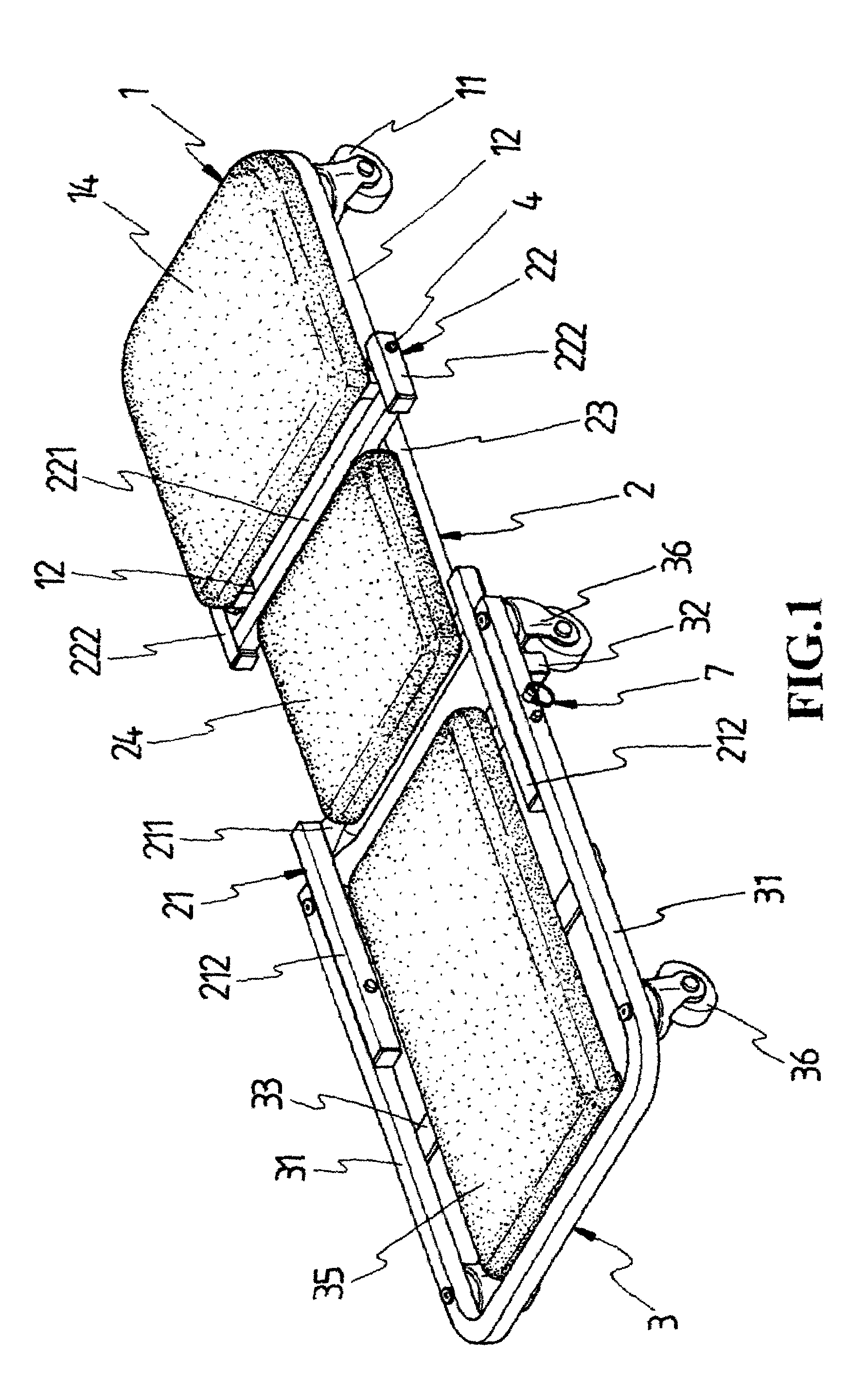
[0020]Referring to FIG. 1 and FIG. 2, the present invention is a two-way caster bench which mainly includes a front chair frame 1, a middle chair frame 2 and a rear chair frame 3.

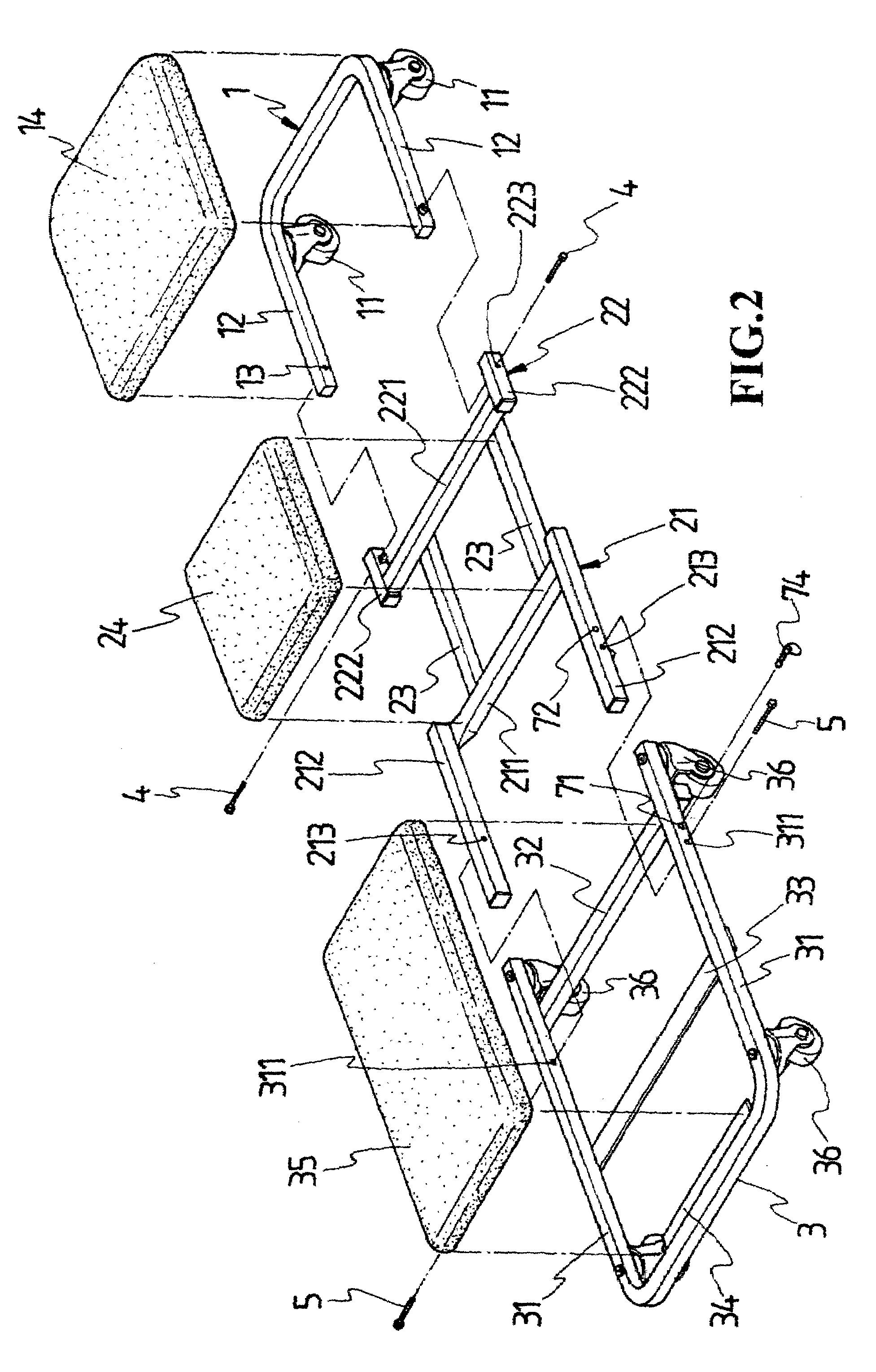
[0021]Referring to FIG. 2, the front chair frame 1 is a U-shaped frame made by folding a single bar or welding a number of bars together, in which two casters 11 are installed at two pre-selected locations in the front lateral portion thereof. Each of the free ends of lateral bars 12 of the U-shaped frame is provided with a pivot hole 13 which goes through the lateral bars in a direction parallel to the central transverse bar of the U-shaped frame. A cushion 14 is mounted on the upper side of the front chair frame 1.

[0022]Referring to FIG. 2, the middle chair frame 2 mainly includes a long U-shaped frame 21 and a short U-shaped frame 22, each made by folding a single bar or welding a number of bars together. The long and short U-shaped frames, placed back to back with the free ends of their longer and short...


PUM


Abstract

A two-way caster bench comprises a front chair frame, a middle chair frame and a rear chair frame. The front chair frame is a U-shaped frame having a predetermined number of casters installed underneath, whose free ends are pivotally connected with the middle chair frame. The middle chair frame is composed of two U-shaped frames connected by a pair of connecting bars, with the free ends facing outwardly. One U-shaped frame is for a pivotal connection to the front chair frame, and another is for a pivotal connection to the rear chair frame. The rear chair frame is also a U-shaped frame having a predetermined number of casters installed underneath, the bottom of which is provided with a transverse bar for supporting the middle chair frame as it is folded toward the rear chair frame. Each of the chair frames is provided with a cushion.

Description

BACKGROUND OF THE INVENTION[0001](a) Field of the Invention[0002]The present invention relates to two-way caster benches, and more particularly to a two-way caster bench that is easily convertible between a folded configuration for sitting and a flat configuration for lying and is freely movable on the ground.[0003](b) Description of the Prior Art[0004]Work-related chairs of the prior art are for facilitating working under unusual situations, such as maintenance work under vehicles or machines. To fit into these situations, they are designed to be a flat bench. There is however another type of work-related chairs for people to step on. In this case, the chairs are designed to be of an upright configuration. Since the conventional work-related chairs are either a lying bench or a stepping chair, a work place sometimes has to be provided with these two types of chairs, which waste available workspace and increase production cost.SUMMARY OF THE INVENTION[0005]Accordingly, the primary o...

Claims


Application Information

Patent Timeline
Patent Type & Authority Patents(United States)
IPC IPC(8): B25H5/00
CPCB25H5/00
Inventor LIU, GUANG-BIN
Owner SHINN FU
Why Eureka
Try Eureka