
Plasma arc torch

a technology of arc torch and arc plate, which is applied in the field of arc torch, can solve the problems of prolonging the service life of the torch components, and achieve the effect of improving the cooling characteristics of the electrode and/or the nozzle, and facilitating safety

Active Publication Date: 2005-11-29
THE ESAB GROUP
View PDF77 Cites 41 Cited by
  • Summary
  • Abstract
  • Description
  • Claims
  • Application Information

AI Technical Summary

Benefits of technology

The present invention provides a plasma torch with improved cooling for the electrode and nozzle. It also ensures safety and precision in assembly and reassembly of the torch. The torch has a movable member and a piston member that can move the electrode between an inoperable position and an operable position. The electrode has a radially outward-extending medial flange that comes into contact with the tubular member when the electrode is in the operable position. This design helps to prevent damage to the torch during use.

Problems solved by technology

Cooling of the electrode and nozzle may provide, for example, greater plasma stability and cutting performance, and may also lengthen the service life of the torch components.

Method used


Image

  • Plasma arc torch
  • Plasma arc torch
  • Plasma arc torch

Examples


Embodiment Construction

[0012]The present inventions now will be described more fully hereinafter with reference to the accompanying drawings, in which some, but not all embodiments of the invention are shown. Indeed, these inventions may be embodied in many different forms and should not be construed as limited to the embodiments set forth herein; rather, these embodiments are provided so that this disclosure will satisfy applicable legal requirements. Like numbers refer to like elements throughout.

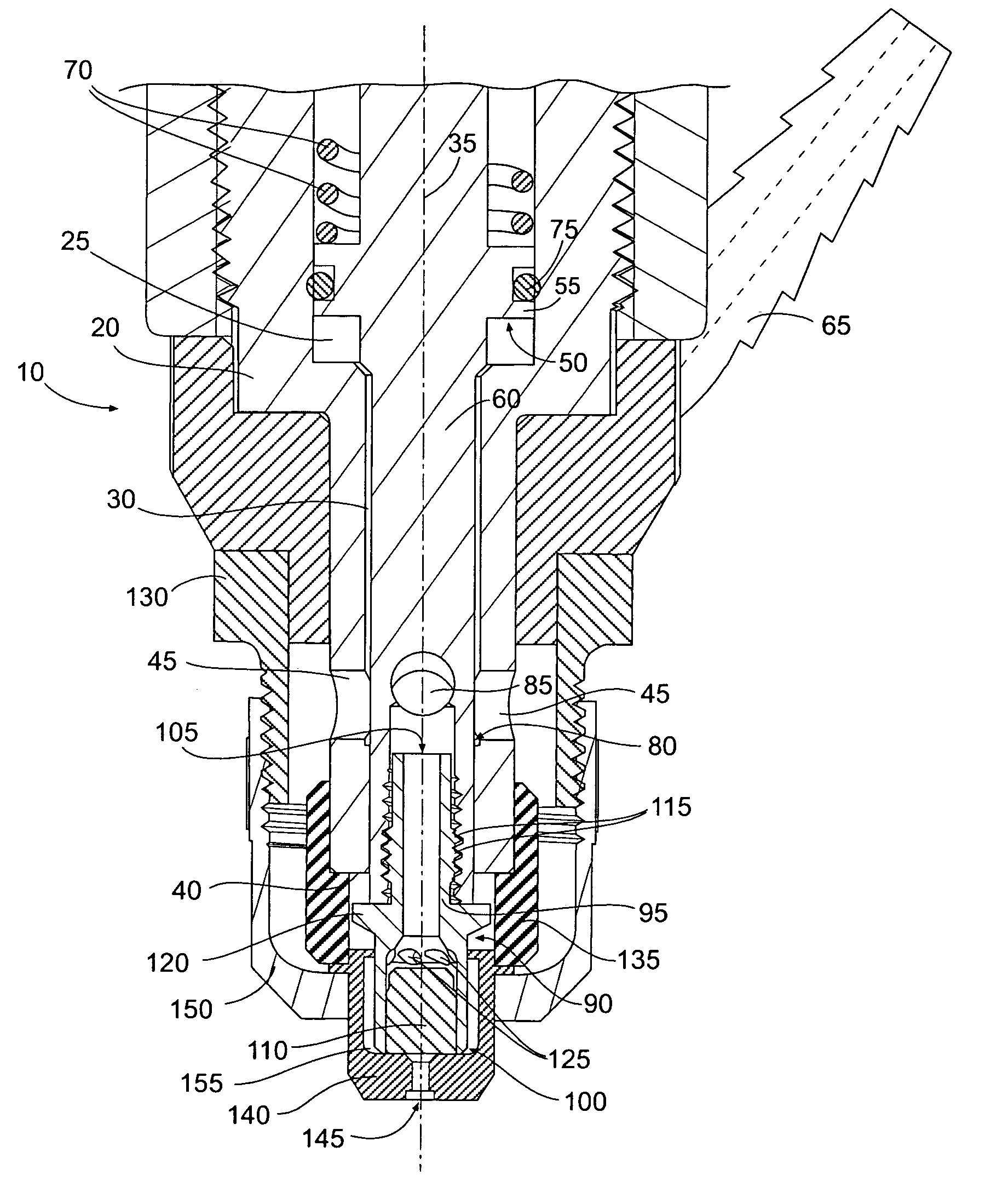
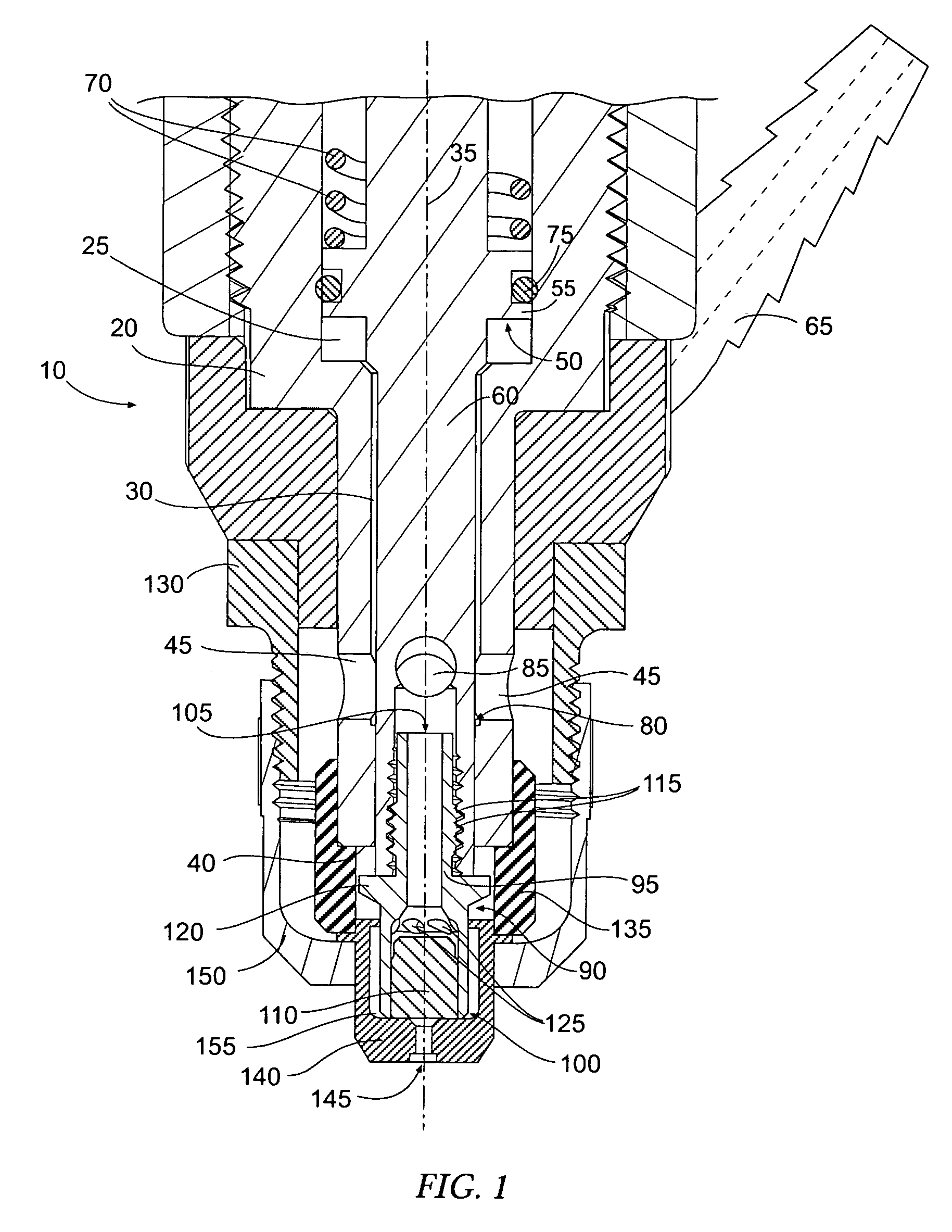
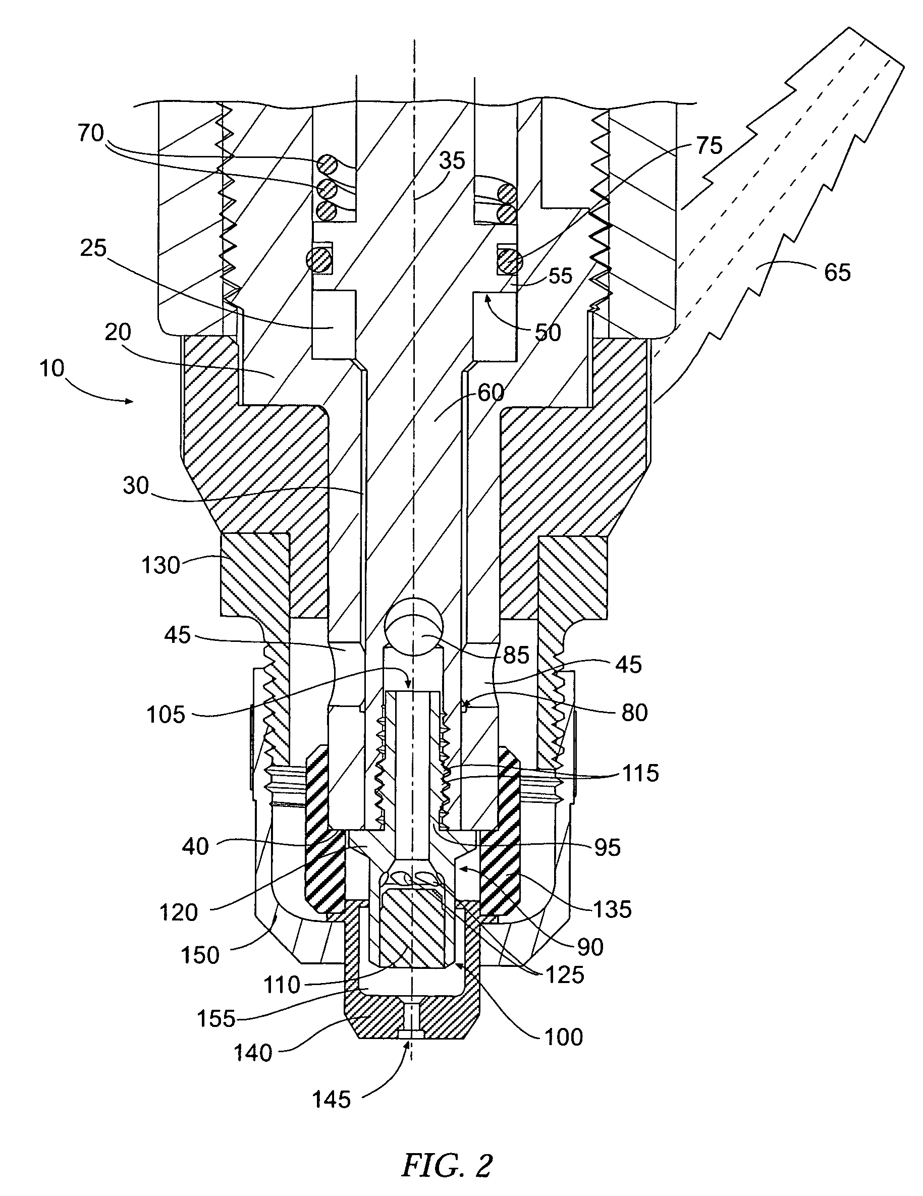
[0013]FIG. 1 illustrates a plasma arc torch according to one embodiment of the present invention, the torch being indicated generally by the numeral 10. Such a torch 10 may be, for example, a blowback or touch-start type torch incorporating improved electrode cooling and safety provisions. As shown, the torch 10 includes a tubular member or housing 20 defining a bore comprising axial piston bore 25 extending to a smaller axial shaft bore 30 along an axis 35. The shaft bore 30 ends at an end surface 40 of the tu...


PUM

PropertyMeasurementUnit
pressureaaaaaaaaaa
plasma stabilityaaaaaaaaaa
sizeaaaaaaaaaa

Abstract

A plasma torch is provided having a tubular member defining a bore extending axially between first and second ends, and nozzle engaged with the first end. A movable member is engaged in the tubular member bore, and includes a first end disposed toward the nozzle and a second end, with a piston member engaged therewith away from the first end. An electrode has a first portion defining a bore and is received by the movable member first end. The electrode has a second portion extending outwardly from the movable member first end toward the nozzle, and a radially outward-extending medial flange between the first and second portions axially outward of the movable member first end. The electrode is movable between an inoperable position in contact with the nozzle and an operable position separated from the nozzle and the medial flange in contact with the tubular member first end.

Description

BACKGROUND OF THE INVENTION[0001]1. Field of the Invention[0002]The present invention relates to a plasma arc torch and, more particularly, to a plasma arc torch with improved electrode cooling and / or safety provisions.[0003]2. Description of Related Art[0004]Blowback type plasma torches are generally configured such that an electrode and a nozzle can be brought into contact with each other to ignite an arc, whereafter, the electrode is separated from the nozzle so as to draw the arc therebetween. A fluid, such as air, is concurrently provided under pressure through the nozzle, wherein the air flow interacts with the drawn arc so as to form a plasma. The plasma flowing through the nozzle is then directed at a workpiece to perform a cutting function.[0005]In some instances, the fluid for forming the plasma is also used to cool the electrode and nozzle. That is, the formation of the plasma generally requires a limited amount of, for example, air. As such, the remainder of the fluid ca...

Claims


Application Information

Patent Timeline
Patent Type & Authority Patents(United States)
IPC IPC(8): B23K9/00B23K10/00B23K10/02B23K31/02H05H1/34
CPCH05H1/34H05H2001/3489H05H1/3489
Inventor GRIFFIN, DAVID CHARLES
Owner THE ESAB GROUP
Learn More