
Method and system for compensating for wheel wear on a train

a technology for compensating and wearing wheels, applied in the field of railways, can solve the problems of significant errors, complex process for controlling the movement of trains in a modem environment, and change in the radius of wheels over time, and achieve the effect of minimizing known errors in the positioning system

Inactive Publication Date: 2005-11-29
SIEMENS MOBILITY INC
View PDF68 Cites 18 Cited by
  • Summary
  • Abstract
  • Description
  • Claims
  • Application Information

AI Technical Summary

Benefits of technology

[0011]In another aspect of the invention, the data used for the comparison between the speeds / distances indicated by the positioning system and by the rotation data is collected over a long distance to minimize known errors in the positioning system. In yet another aspect of the invention, a total distance traveled is calculated using an integration technique by adding a plurality of linear differences in successive positions reported by the positioning system over short periods of time. This technique is particularly advantageous when performed over curved sections of track.

Problems solved by technology

Controlling the movement of trains in a modem environment is a complex process.
However, the radius of a wheel changes over time due to wheel wear.
This error is significant.

Method used


Image

  • Method and system for compensating for wheel wear on a train
  • Method and system for compensating for wheel wear on a train
  • Method and system for compensating for wheel wear on a train

Examples


Embodiment Construction

[0020]The present invention will be discussed with reference to preferred embodiments of train control systems. Specific details, such as wheel sizes and types of positioning systems, are set forth in order to provide a thorough understanding of the present invention. The preferred embodiments and specific details discussed herein should not be understood to limit the invention.

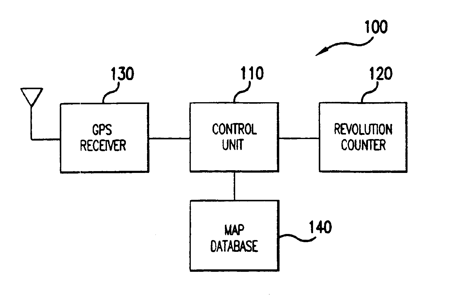
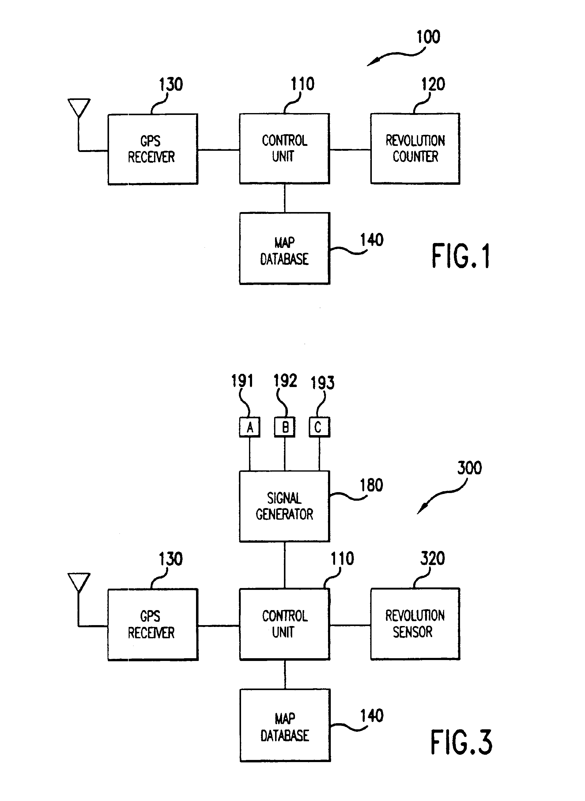
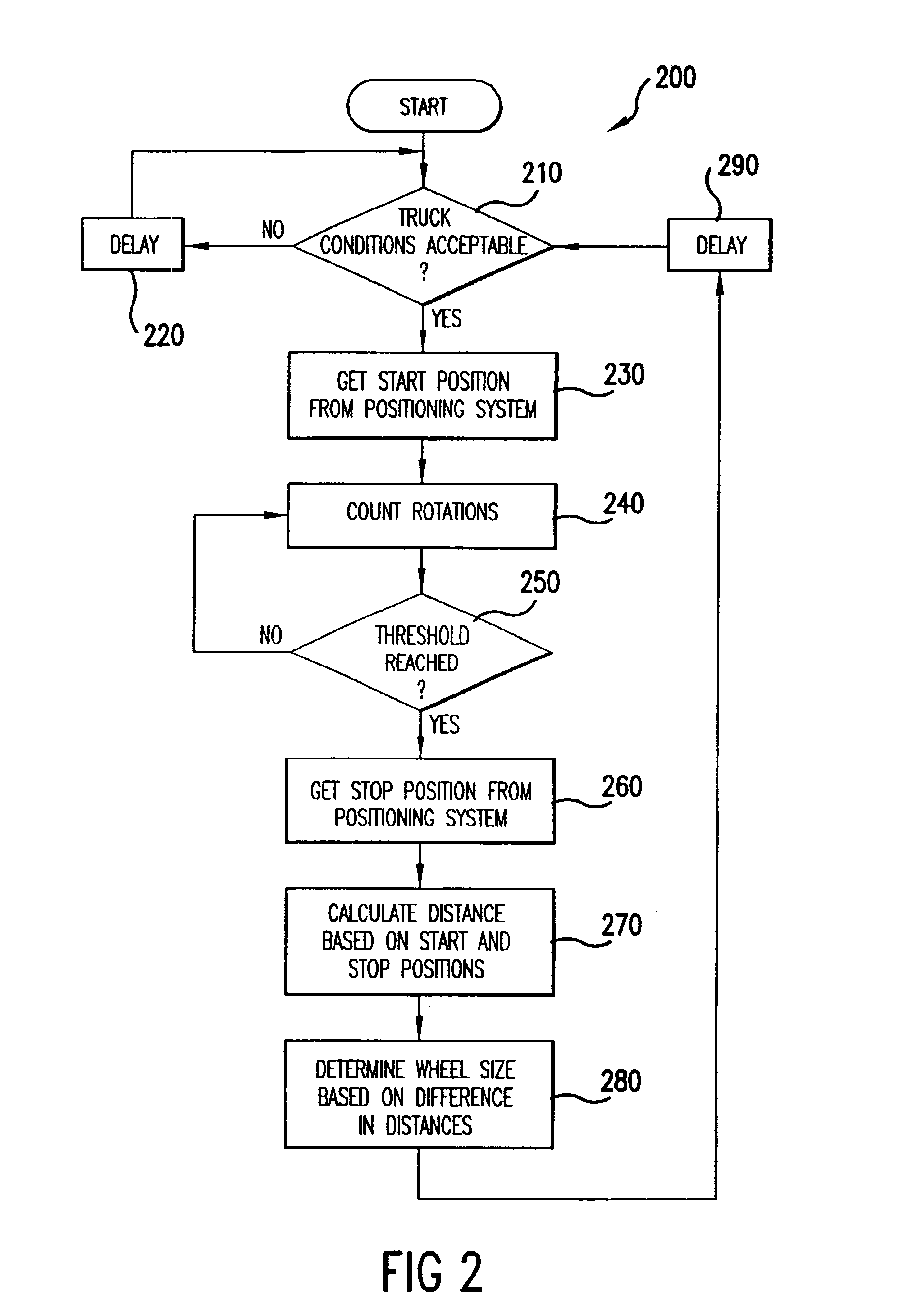
[0021]Referring now to the drawings, wherein like reference numerals designate identical or corresponding parts throughout the several views, FIG. 1 is a logical block diagram of a train control system 100 according to the present invention. The system 100 includes a control unit 110, which typically, but not necessarily, includes a microprocessor. The control unit 110 is connected to a revolution counter 120. The revolution counter 120 measures rotation of a locomotive wheel (not shown in FIG. 1) on a train. The revolution counter 120 may be of any type, including mechanical, magnetic, and optical. The revol...


PUM


Abstract

A method and system for compensating for wheel wear uses position and / or speed information from an independent positioning system to measure some distance over which the train has traveled. Wheel rotation information and / or distance and speed from a wheel sensor over the distance is also collected. The wheel rotation information and distance and / or speed information are then used to determine the size of the train wheels and / or a correction factor that can be used to correct the information from the wheel sensor for wheel wear. The method is performed periodically to correct for changes in wheel size over time due to wear so that the wheel rotation information can be used to determine train position and speed in the event of a positioning system failure.

Description

[0001]This application is a Continuation-In-Part of application Ser. No. 10 / 157,874, filed May 31, 2002, now U.S. Pat. No. 6,701,228, the entirety of which is incorporated herein by reference, and a Continuation-In-Part of application Ser. No. 10 / 609,377, filed Jul. 1, 2003, the entirety of which is also incorporated by reference herein.BACKGROUND OF THE INVENTION[0002]1. Field of the Invention[0003]The invention relates to railroads generally, and more particularly to a system and method for determining wheel size to compensate for wheel wear.[0004]2. Discussion of the Background[0005]Controlling the movement of trains in a modem environment is a complex process. Collisions with other trains must be avoided and regulations in areas such as grade crossings must be complied with. The pressure to increase the performance of rail systems, in terms of speed, reliability and safety, has led to many proposals to automate various aspects of train operation. For example, positive train cont...

Claims


Application Information

Patent Timeline
IPC IPC(8): B61L25/02G01C22/02G06F7/00
CPCB61L25/021B61L25/023B61L25/025B61L25/026G01C22/02B61L2205/04
Inventor KANE, MARK EDWARDSHOCKLEY, JAMES FRANCISHICKENLOOPER, HARRISON THOMAS
Owner SIEMENS MOBILITY INC
Learn More