Carton

a technology of cartons and handles, applied in the field of cartons, can solve the problems of difficult gripping of the handle straps, and achieve the effect of excellent physical strength and facilitation of the formation of the hand room under the strap handl

Inactive Publication Date: 2005-12-06
MEADWESTVACO PACKAGING SYST LLC
View PDF22 Cites 21 Cited by
  • Summary
  • Abstract
  • Description
  • Claims
  • Application Information

AI Technical Summary

Benefits of technology

[0005]According to the present invention, there is provided a carton including a base panel, a pair of side wall panels hingedly connected to the opposed side edges of the base panel, a top panel hingedly connected to the upper edge of one of the side wall panels, a pair of end flaps hingedly connected to the opposed end edges of the top panel and extending toward the base panel, a finger aperture defined in the top panel, and a strap handle disposed slidably with respect to the underside of the top panel and exposed to view within the finger aperture. The strap handle includes a main strap having a medial portion extending parallel to the opposed side edges of the top panel. The opposite ends of the main strap are hingedly connected to the end flaps along fold lines. Each of these fold lines extends parallel to a notional line extending between the top and base panels. Because the strap handle is disposed slidably with respect to the top panel and exposed to view within the finger, a part of the strap handle may bow upwardly and protrude through the finger aperture when the end flaps are folded into their closing positions and thereby the strap handle becomes slack. By this means, formation of a hand room under the strap handle can be facilitated.
[0006]According to a preferred embodiment of the invention, the strap handle may include an outside strap disposed along the upper surface of the main strap. The outside strap may be formed from the top panel, extend longitudinally across the finger aperture and connected at its opposite ends to the top panel by tear lines respectively. The outside strap prevents the uncoated side of the handle material of the main strap from being exposed to view.
[0007]According to another preferred embodiment of the invention, the strap handle may include a reinforcing strap extending along and hingedly connected to the main strap. The reinforcing strap may be adhesively secured to the main strap. The reinforcing strap may be disposed at the underside of the main strap. This arrangement allows the main strap to be directly secured to the inside surfaces of the end flaps without the reinforcing strap being interposed therebetween, which in turn allows a greater surface of the end portions of the main strap effectively secured to the end flaps. Accordingly, it is insured that the strap handle is strongly attached to the end flaps.
[0008]According to a further preferred embodiment, a second top panel may be hingedly connected to the upper edge of the other side wall panel and it is secured to the underside of the first top panel. The strap handle may include a secondary strap formed from the second top panel. The secondary strap may extend along the underside of the main strap. In such an arrangement, the strap handle is less bulky than it would be when the secondary strap were formed from material adjacent to the first top panel.
[0009]According to a still further preferred embodiment, the reinforcing strap may be secured to the upper surface of the main strap, the outside strap may be secured to the upper surface of the reinforcing strap, and the secondary strap may be secured to the underside of the main strap. This arrangement provides a handle with an excellent physical strength because each strap of the strap handle is secured to a next adjacent strap would.

Problems solved by technology

This is a drawback from a standpoint of an end user because it is simply difficult to grip the handle strap.

Method used


Image

  • Carton
  • Carton
  • Carton

Examples


Embodiment Construction

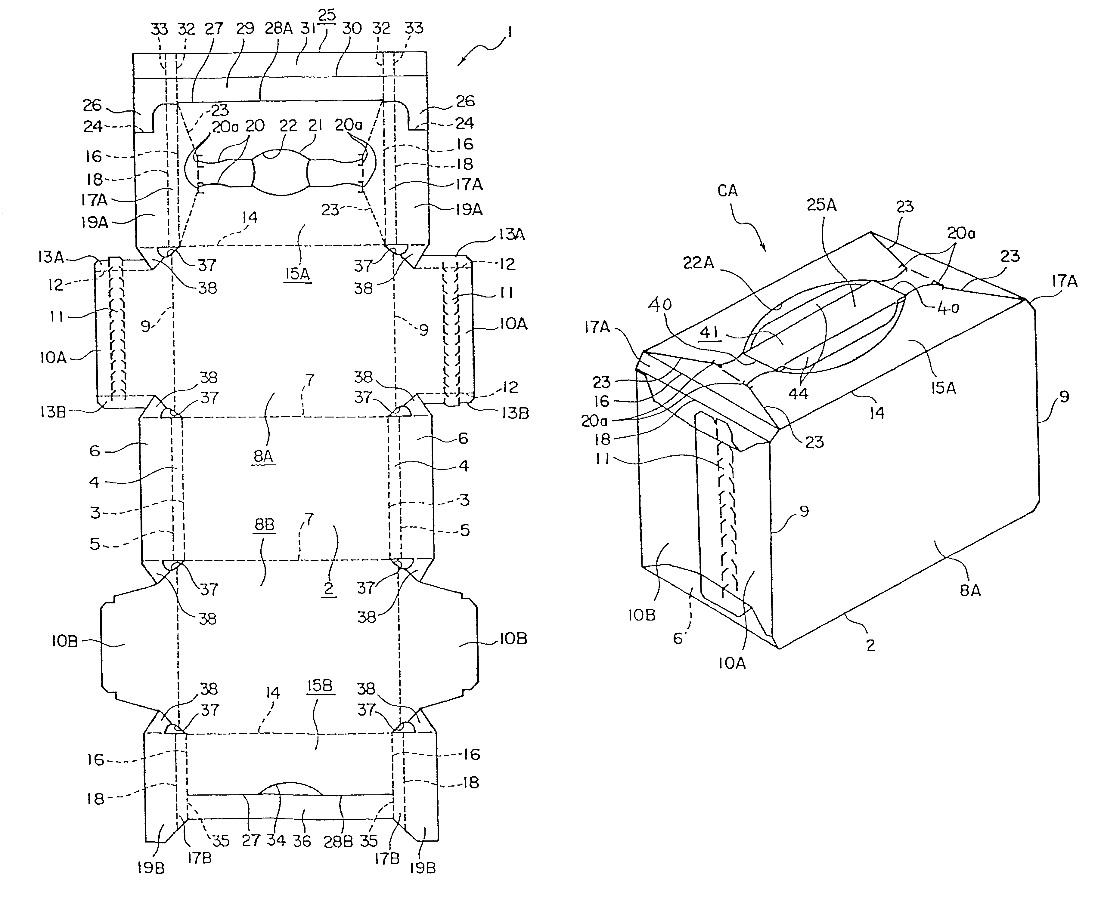
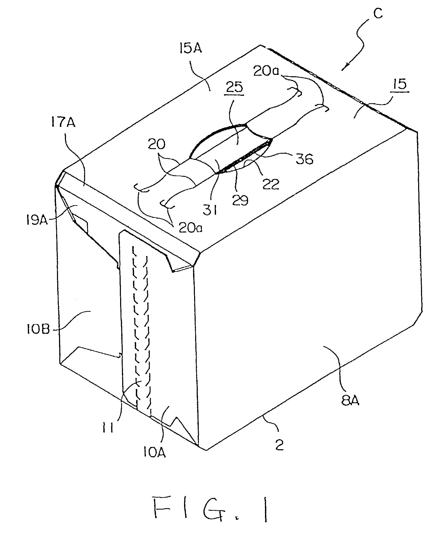
[0018]FIGS. 1–3 illustrate the first embodiment of the present invention, in which FIG. 3 shows a blank from which the carton of the invention is erected. The blank is essentially rectangular in shape and is formed, in this embodiment, of paperboard. However, the blank may be formed of similar foldable material such as a plastic sheet. The blank 1 of this embodiment is designed for packaging twelve 500-ml beer cans arranged in three rows of four cans each. The blank 1 includes a rectangular base panel 2 located about midway along the length of the blank. A pair of bevelled panels 4 are connected to the opposite end edges of the base panel 2 along fold lines 3 respectively. When the blank is erected into a carton, the bevelled panels 4 are disposed at an angle with respect to the base panel 2. The inclination angle of each bevelled panel 4 is designed to correspond to the shape of each can that is to be packaged in the carton. A pair of lower end flaps 6 are connected to the bevelled...


PUM

PropertyMeasurementUnit
physical strengthaaaaaaaaaa
shapeaaaaaaaaaa
lengthaaaaaaaaaa

Abstract

A carton includes a base wall, a pair of side walls hingedly connected to opposed side edges of the base wall, a first top panel hingedly connected to an upper edge of one of the side walls, a pair of end flaps hingedly connected to opposed end edges of the top panel and extending toward the base wall, a finger aperture defined in the top panel, and a strap handle disposed slidably with respect to an underside of the top panel and exposed to view within the finger aperture. The strap handle includes a main strap having a medial portion extending parallel to opposed side edges of the top panel. The opposite ends of the main strap are hingedly connected to the end flaps along fold lines. Each fold line extends parallel to a notional line extending between the top panel and the base wall.

Description

[0001]This is a continuation of international application No. PCT / US01 / 45113, filed Oct. 24, 2001, which is hereby incorporated by reference.BACKGROUND OF THE INVENTION[0002]This invention relates generally to cartons useful to package articles such as cans, and more particularly to a carton having a strap handle by which it may be carried.[0003]A type of conventional carton includes a base panel, a pair of side wall panels hingedly connected to the opposed side edges of the base panel, a top panel hingedly connected to the upper edge of one of the side wall panels and a pair of partial end wall panels foldably connected to the opposed end edges of the top panel and extending toward the base panel. Japanese Patent Publication No. 9-502148 discloses a carton of the above type, having a handle strap connected to the partial end wall panels along vertical fold lines so that the carton may be carried by the strap handle. The handle may be formed from the material located adjacent to the...

Claims


Application Information

Patent Timeline
Patent Type & Authority Patents(United States)
IPC IPC(8): B65D5/46B65D5/462B65D71/00B65D71/36
CPCB65D71/36B65D2571/00141B65D2571/00469B65D2571/00524B65D2571/00543B65D2571/00549B65D2571/00567B65D2571/0066B65D2571/00728
Inventor IKEDA, TAMIO
Owner MEADWESTVACO PACKAGING SYST LLC
Why Eureka
Try Eureka