Backrest

Inactive Publication Date: 2005-12-06
IWI
View PDF7 Cites 59 Cited by
  • Summary
  • Abstract
  • Description
  • Claims
  • Application Information

AI Technical Summary

Benefits of technology

[0011]A backrest according to the present invention comprises a molded support, a series of adjustable straps extending across the molded support, a releasable lock means for engaging each strap and maintaining a set relationship of each strap relative to the molded support when the lock means is i

Problems solved by technology

Lower back problems continue to be of concern to a large percentage of people.
Acute lower back pain can severely restrict the activities of the inflicted person, as well as affect their mental outlook.
In some cases, improper back support can contribute or prolong back pain.
Customized back supports are cer

Method used


Image

  • Backrest
  • Backrest
  • Backrest

Examples


Embodiment Construction

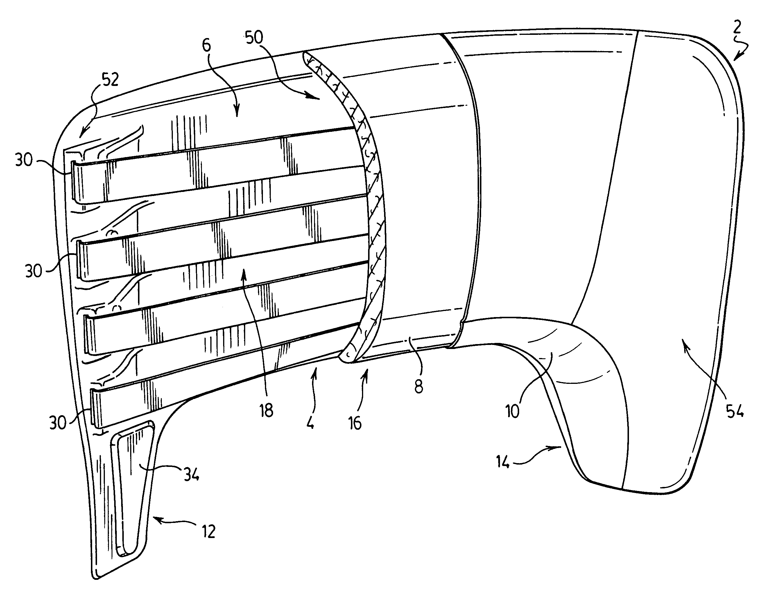
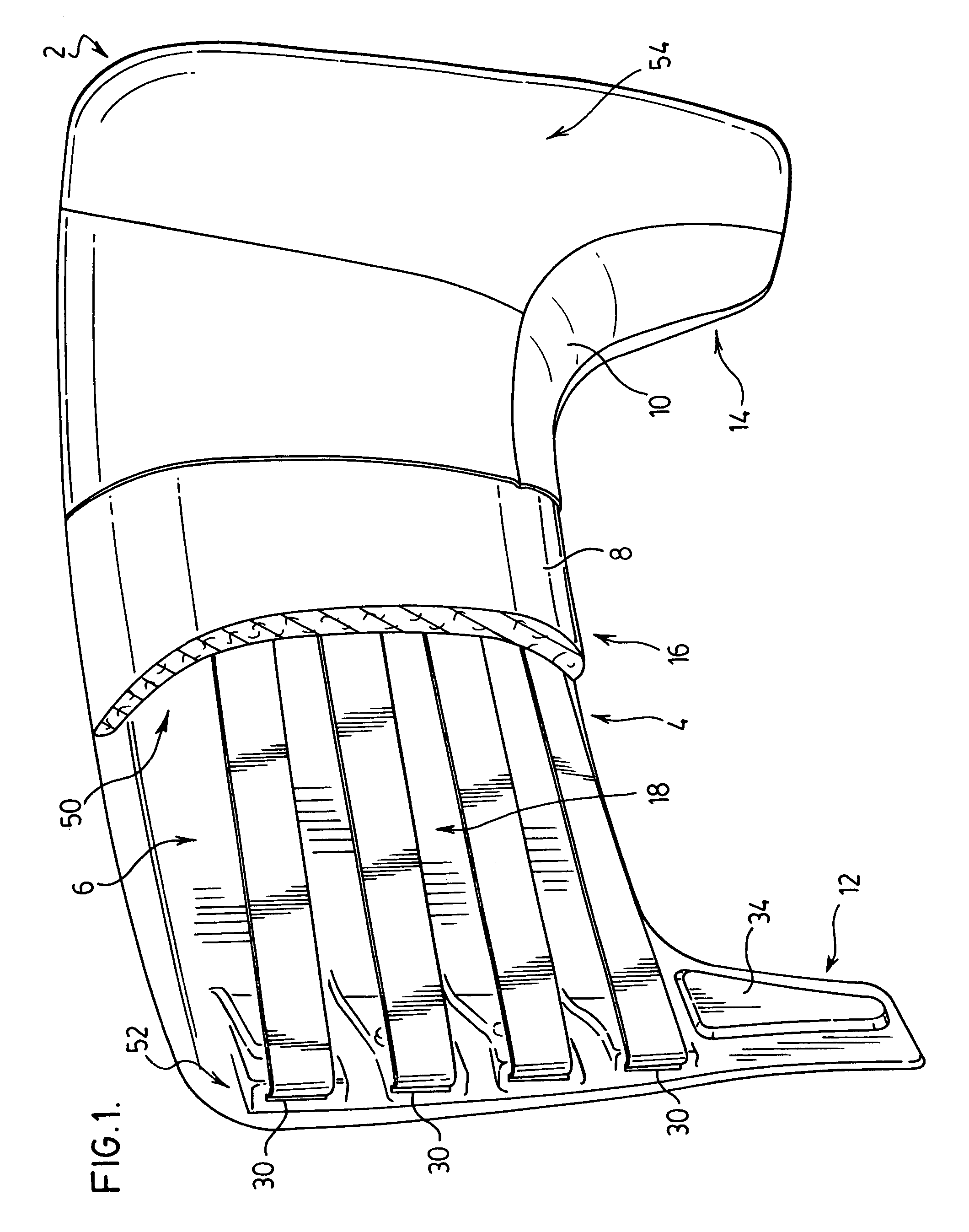
[0018]The backrest 2 as shown in FIG. 1 is of a composite construction and includes a molded backrest support 4, a series of adjustable straps 6, a foam cushion overlay 8 (partially shown), and a contoured cover 10 (partially shown). The molded backrest support 4 includes the intermediate joining section 50 and opposed side support sections 52 and 54 which are connected to and slightly forward of the intermediate joining section 50. This structure defines a shallow U-shaped cavity and a series of adjustable straps 6 extend across this cavity to provide customized support for a person's lower back. Each of the side support sections have downwardly extending legs 12 and 14 positioned on opposite sides of the backrest. The intermediate joining section 50 is located above the legs and in combination with these legs define an open bottom cavity 16. The straps 6 in combination with the intermediate joining section define a raised adjustable back support 18.

[0019]The intermediate joining s...


PUM


Abstract

An adjustable backrest has a series of adjustable straps extending across a front opening cavity of a backrest support. The straps are held in a locked, fitted position by a series of buckles at one side of the backrest which engage and lock the straps. Each strap is acted on by a bias arrangement and urges the straps to a drawn position across the front open cavity. This drawn position is an initial setup position that allows fitting of the backrest for a particular user.

Description

FIELD OF THE INVENTION[0001]The present invention relates to backrests typically used in combination with chair seats and other seating support structures. In particular, the invention is directed to a backrest support which is easily adjusted to accommodate different spinal profiles.BACKGROUND OF THE INVENTION[0002]Lower back problems continue to be of concern to a large percentage of people. Acute lower back pain can severely restrict the activities of the inflicted person, as well as affect their mental outlook. Many back problems are often the result of muscle strain and are alleviated with or without treatment in approximately six to ten weeks. Proper back support can assist in the healing process and promote better posture (less back strain) on an ongoing basis.[0003]In some cases, improper back support can contribute or prolong back pain. Many desk chairs, office task chairs, car seats, etc. are not specifically designed to provide proper support to a person's lower back. It ...

Claims


Application Information

Patent Timeline
IPC IPC(8): A47C7/02A47C7/46A47C31/00
CPCA47C7/46
Inventor RHODES, PAUL
Owner IWI
Why Eureka
Try Eureka