Hollow rotor blade for the turbine of a gas turbine engine, the blade being fitted with a "bathtub"

a technology of gas turbine engine and hollow blade, which is applied in the direction of blade accessories, machines/engines, mechanical apparatus, etc., can solve the problems of increasing clearance, limiting the flow of cooling air that reaches the tip of the rim, and no longer being able to provide hollow blades, so as to increase the overall performance of the turbine and prevent the flow through the clearance

Active Publication Date: 2008-04-01
SN DETUDE & DE CONSTR DE MOTEURS DAVIATION S N E C M A
View PDF7 Cites 38 Cited by
  • Summary
  • Abstract
  • Description
  • Claims
  • Application Information

AI Technical Summary

Benefits of technology

[0018]Consequently, an object of the present invention is to provide a hollow rotor blade for the turbine of a gas turbine engine, of the above-specified type, that enables the end of the blade to be cooled in a manner that is sufficient so as to increase its reliability without reducing the aerodynamic and high temperature strength performance of the blade.
[0021]This solution also presents the additional advantage of not only bringing the outlets of the cooling channels to the free end of the blade, but also making it possible to provide a pressure side surface for the blade that is made concave at the tip of the blade due to the fact that the outside face of the end portion is inclined.
[0022]This particular shape is preferably present along the entire profile from the leading edge to the trailing edge. It makes it possible to prevent a flow through the clearance at the tip of the blade. The inclination of the wall towards the pressure side at the tip of the blade leads to strong separation of the boundary layer at the tip of the blade. As a result, the flow section as “seen” by the flow between the tip of the blade and the case is made smaller by the separation of the boundary layer being increased in size: this reduces the flow that is “lost” into the gap between the tip of the blade and the casing.
[0023]Thus, this projecting end portion with its inclined outside face makes it possible to obtain improvements that are not only thermal but also that are hydraulic at the tip of the blade, as well as mechanically strengthening the tip of the blade at the location of the open cavity or “bathtub”.
[0024]Thus, by means of a solution of the present invention, it is possible to increase the overall performance of the turbine.

Problems solved by technology

In addition, that solution puts a very severe limit on the flow of cooling air that reaches the tip of the rim, since the major fraction of the flow leaves the internal cooling passage via the first segments of the cooling channels and penetrates directly into the cavity without reaching the outside face of the pressure side wall.
However, given the ever-increasing operating temperatures of turbines, those solutions no longer make it possible to provide a hollow blade with the end of the blade being cooled in satisfactory manner.
Consequently, since the thicknesses of material are large, the more the temperature rises because cooling is not so fast, the more these large thicknesses of material prevent sufficient cooling at the tip of the blade to enable the turbine to operate at the desired higher temperatures.
It should be observed that if cooling is insufficient at the end of the blade, local burning can take place that can lead to metal being lost, thereby increasing clearances, and thus harming the aerodynamic efficiency of the turbine.
Likewise, when the rim of the cavity sees its temperature increase excessively, there is observed to be a risk of burning with damage to the metal wall.

Method used


Image

  • Hollow rotor blade for the turbine of a gas turbine engine, the blade being fitted with a "bathtub"
  • Hollow rotor blade for the turbine of a gas turbine engine, the blade being fitted with a "bathtub"
  • Hollow rotor blade for the turbine of a gas turbine engine, the blade being fitted with a "bathtub"

Examples


Embodiment Construction

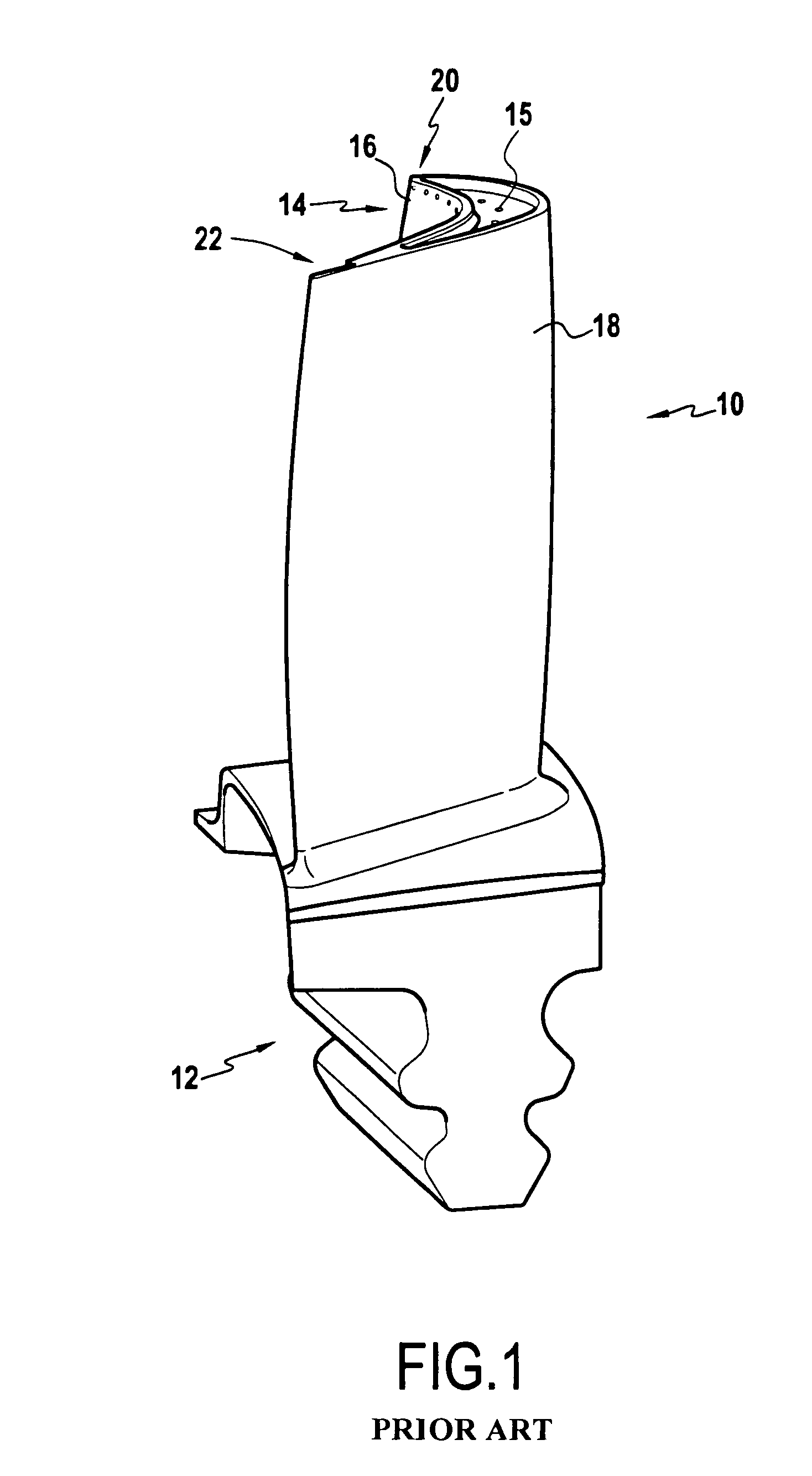
[0039]FIG. 1 is a perspective view showing an example of a conventional hollow rotor blade 10 for a gas turbine. Cooling air (not shown) flows inside the blade from the bottom of the root 12 of the blade in the radial direction (vertically) towards the free end 14 of the blade (at the top of FIG. 1), and then cooling air escapes via an outlet to join the main gas stream.

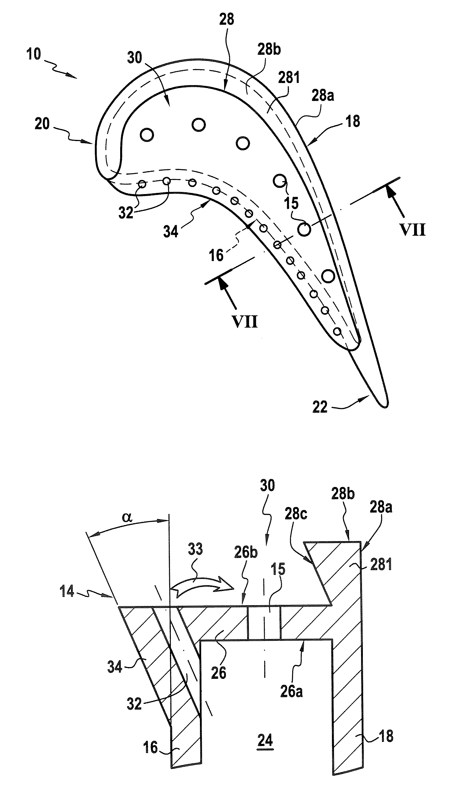
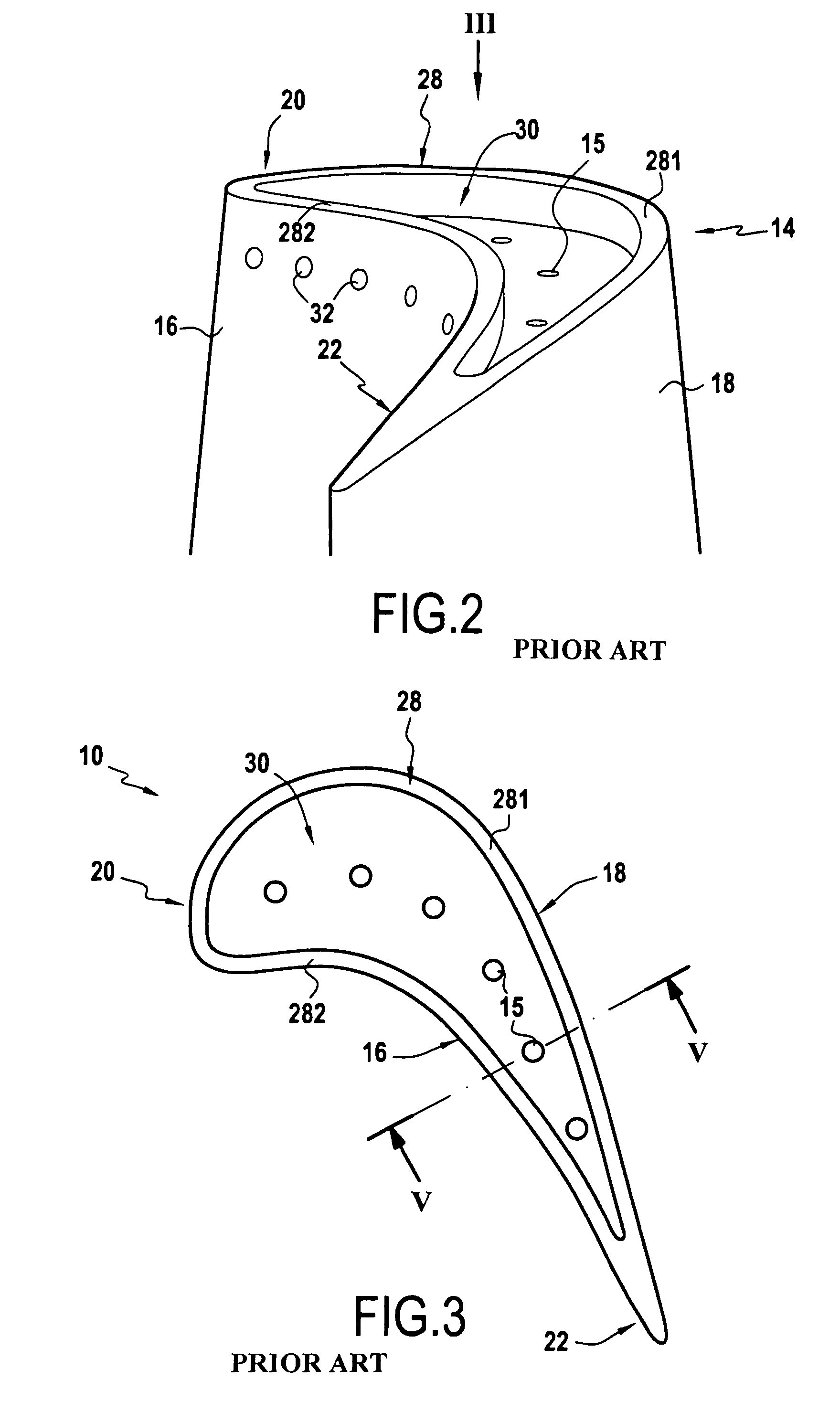
[0040]In particular, as can be seen in FIGS. 2 to 5, this cooling air flows in an internal cooling passage 24 situated inside the blade 10 and terminating at the free end 14 of the blade via through holes 15.

[0041]The body of the blade is shaped so as to define a pressure side wall 16 (to the left in all of the figures) and a suction side wall 18 (to the right in all of the figures). The pressure side wall 16 is generally concave in shape and presents the first face to the hot gas stream, i.e. to the pressure side of the gas, while the suction side wall 18 is convex and presents itself to the hot gas stream subsequen...


PUM


Abstract

A hollow blade has an internal cooling passage, an open cavity situated at the free end of the blade and defined by an end wall extending over the entire end of the blade and by a rim. The blade includes cooling channels connecting the internal cooling passage and the outside face of the pressure side wall. The pressure side wall presents a projecting end portion whose outside face is inclined relative to the outside face of the pressure side wall. The cooling channels are disposed in the end portion, being parallel to the outside face of the end portion so that they open out into the tip of the end portion towards the free end of the blade.

Description

[0001]The invention relates to a hollow rotor blade for the turbine of a gas turbine engine, in particular for a turbine of the high pressure type.[0002]More precisely, the present invention relates to making a hollow blade of the type that includes an internal cooling passage, an open cavity situated at the free end of the blade and defined by an end wall extending over the entire end of the blade and by a rim extending between the leading edge and the trailing edge along at least the suction side wall, and cooling channels connected said internal cooling passage and the outside face of the pressure side wall, said cooling channels being inclined relative to the pressure side wall.BACKGROUND OF THE INVENTION[0003]Cooling channels of this type are intended for cooling the free end of the blade since they enable a jet of cooling air to be delivered from the internal cooling passage towards the end of the blade at the top end of the outside face of the pressure side wall. This jet of ...

Claims


Application Information

Patent Timeline
Patent Type & Authority Patents(United States)
IPC IPC(8): F01D5/20
CPCF01D5/20
Inventor DESCHAMPS, PASCALGIOT, CHANTAL GISELEPOTIER, THOMAS
Owner SN DETUDE & DE CONSTR DE MOTEURS DAVIATION S N E C M A
Why Eureka
Try Eureka