Mattress adapted for supporting heavy weight persons

a mattress and mattress technology, applied in the field of medical mattresses, can solve the problems of frequent body movement or adjustment, poor night's sleep, excessive sag or bottoming of mattresses,

Active Publication Date: 2013-01-29
FXI
View PDF89 Cites 37 Cited by
  • Summary
  • Abstract
  • Description
  • Claims
  • Application Information

AI Technical Summary

Problems solved by technology

Higher compression tends to restrict capillary blood flow, called “ischemic pressure”, which causes discomfort.
Poor body alignment on a mattress also leads to body discomfort, leading to frequent body movement or adjustment during sleeping and a poor night's sleep.
Higher weight persons may cause the mattress to sag excessively or bottom out, particularly at the sacrum supporting region.
A sagging mattress also allows the person's waist to drop relative to the rib cage and hips, and causes stress to muscles, tendons and ligaments.
Such stress may lead to joint pain, particularly lumbar and back pain.
Mattress constructions with springs and heavy supporting structures that may be appropriate for home use are not appropriate for hospitals and clinics.
Such pads or overlays add additional cost to patient care.

Method used


Image

  • Mattress adapted for supporting heavy weight persons
  • Mattress adapted for supporting heavy weight persons
  • Mattress adapted for supporting heavy weight persons

Examples


first embodiment

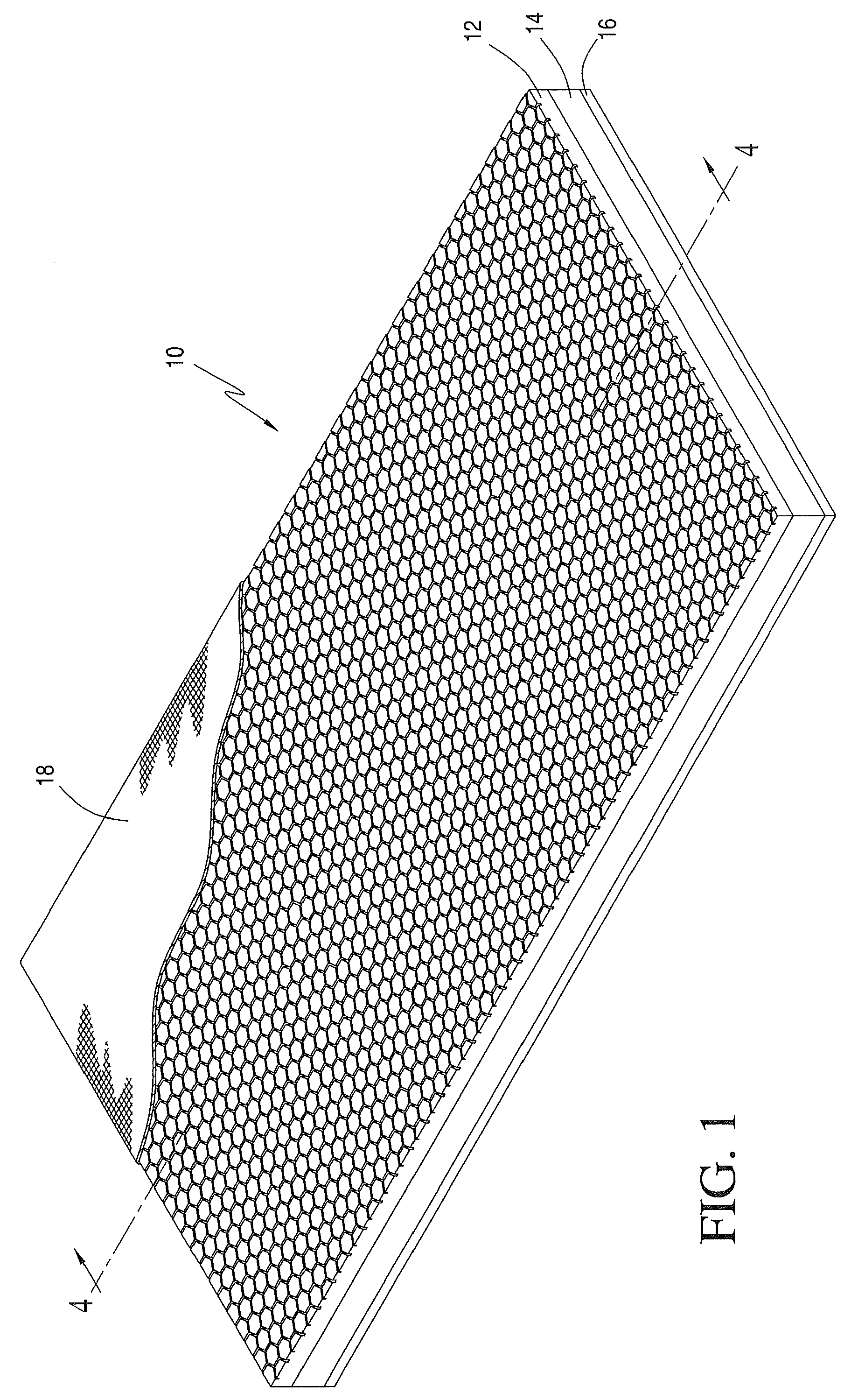
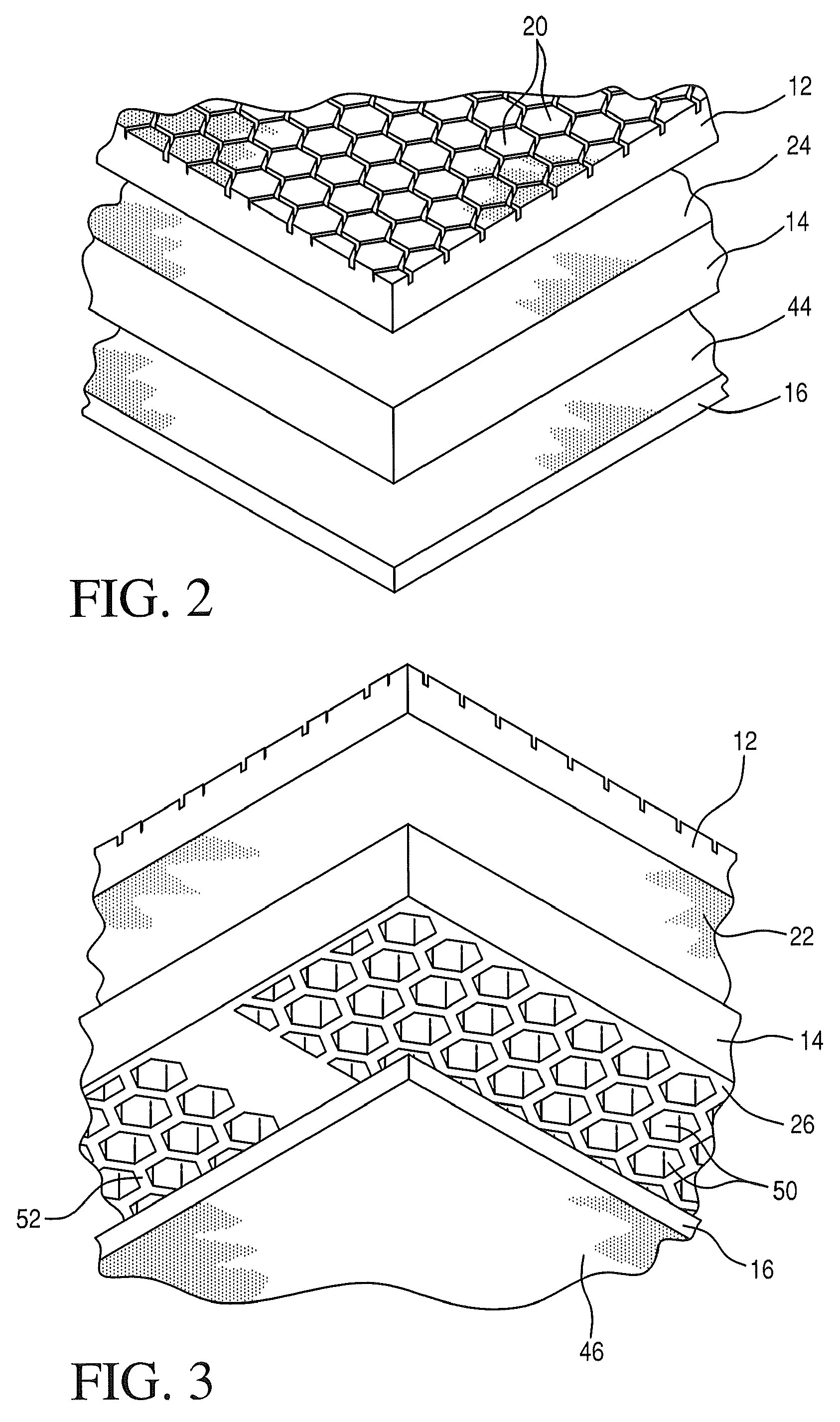
[0040]The top layer 12 of this first embodiment comprises a viscoelastic foam. Representative viscoelastic foams include foams with glass transition temperatures above −20 C and with ball rebound values of less than approximately 20%. The viscoelastic foam of the top layer 12 may have a density in the range of 1.5 pcf to 10.0 pcf, more particularly 3.0 pcf to 6.0 pcf.

[0041]Viscoelastic or slow-recovery foams frequently have lower air permeabilities, which leads to increased heat build-up when such foams are used in mattress constructions. Higher skin temperatures may accelerate pressure ulcer formation. In one embodiment, the viscoelastic foam used for the top layer 12 is an open cell foam with an air permeability of at least about 60 ft3 / ft2 / min, preferably at least about 100 ft3 / ft2 / min. Foams with such air permeability help to maintain a reclining person's skin temperature closer to normal body temperatures, e.g., 96-100° F.

[0042]The top surface of the top layer 12 preferably has...

third embodiment

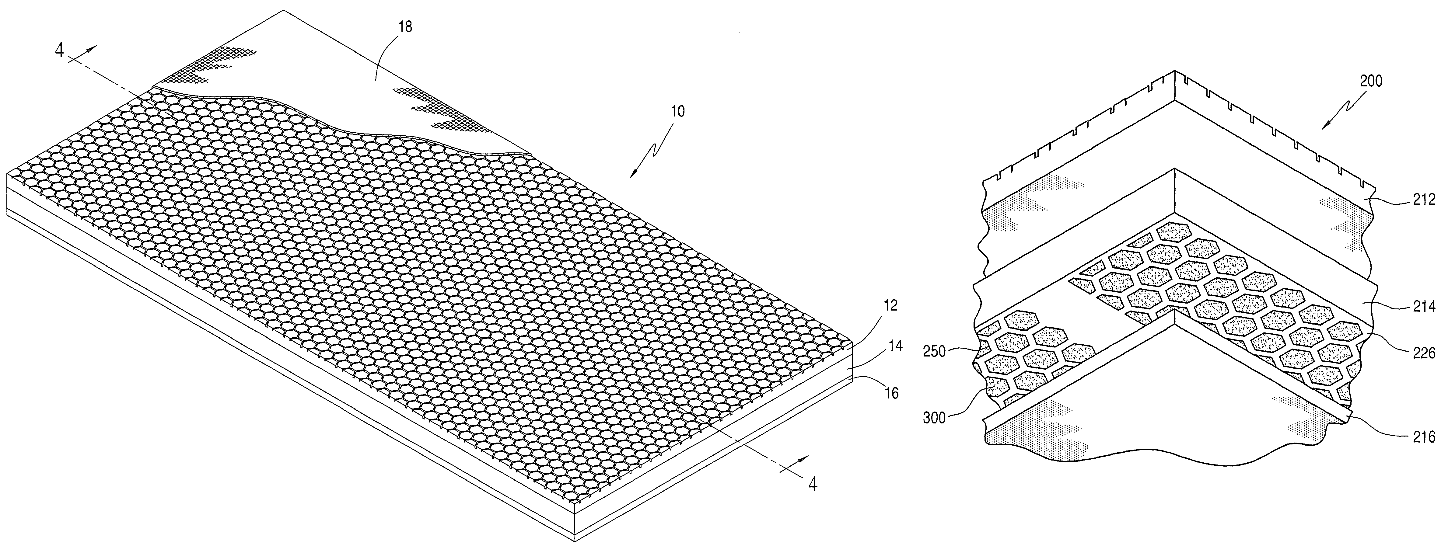
[0071]Referring to FIG. 9, a mattress construction 200 of a third embodiment has a top layer 212, a core or middle layer 214, and a bottom layer 216. The three layers 212, 214, 216 form in combination the sleeping mattress 200.

[0072]The bottom surface 226 of the core layer 214 is generally flat or substantially planar. As shown in FIGS. 9 and 10, the bottom surface 226 has regions from which foam material has been extracted to form multiple cavities 250 separated by upstanding sidewalls 252. The foam material has not been cut away at the upstanding sidewalls 252. The cavities 250 extend to a depth within the thickness of the core layer 214 and terminate in cavity bases 254. The core layer 214 may be provided with a desired thickness. Particularly, if the core layer 214 has a thickness of about 3 inches, the cavities 250 extend to depths of from about 0.25 to 2.6 inches. The cavities in a region may have the same or different depths. Alternatively, the cavities in one region may have...


PUM


Abstract

A mattress constructed with multiple foam layers joined together provides reclining support with pressure redistribution for heavy weight persons, particularly those weighing over 350 pounds. The mattress includes: a core layer having a substantially planar top surface and at least two spaced apart regions in a bottom surface from which foam material has been extracted to leave cavities separated by an interconnected network of foam walls, a top layer of viscoelastic foam with an air permeability above 60 ft3 / ft2 / min, and a bottom layer of stiffer supporting foam. The open cavities of the core layer are directed away from the body supporting top surface of the mattress and contain one or more gels.

Description

CROSS-REFERENCE TO RELATED APPLICATION[0001]This application is a continuation-in-part of U.S. Ser. No. 12 / 429,778, filed Apr. 24, 2009, now U.S. Pat. No. 7,886,388.FIELD OF THE INVENTION[0002]The present invention relates to bedding mattresses and medical mattresses that redistribute pressure and reduce incidence of bed sore formation, which we believe will support persons weighing up to 350 pounds and over.BACKGROUND[0003]Prolonged contact between body parts and a mattress surface tends to put pressure onto the reclining person's skin. The pressure tends to be greatest on the body's bony protrusions (such as sacrum, hips and heels) where body tissues compress against the mattress surface. Higher compression tends to restrict capillary blood flow, called “ischemic pressure”, which causes discomfort. The ischemic pressure threshold normally is considered to be approximately 40 mmHg. Above this pressure, prolonged capillary blood flow restriction may cause red spots or sores to form ...

Claims


Application Information

Patent Timeline
Patent Type & Authority Patents(United States)
IPC IPC(8): A47C17/00
CPCA47C27/144A47C27/15
Inventor WARREN, STEPHEN C.NIEDEROEST, BEAT B.COVEY, KERRY LYNNCONTRERAS, JOSE D. M.NETO, MARIO F
Owner FXI
Why Eureka
Try Eureka