Cutting tool and cartridge therefor

a cutting tool and cartridge technology, applied in the field of cutting tools, can solve the problems of limiting the circumferential pitch of the cartridge and consequently of the cutting insert, the presence of threaded bores can weaken the tool body, and the screw part of the broken off screw can become lodged in the threaded bore,

Active Publication Date: 2005-12-06
ISCAR LTD
View PDF11 Cites 45 Cited by
  • Summary
  • Abstract
  • Description
  • Claims
  • Application Information

AI Technical Summary

Problems solved by technology

Not only do threaded bores in the tool body require various metal cutting operations to produce them, or operations, but the mere presence of threaded bores can weaken the tool body.
Furthermore, in the event of damage to the cutting tool, a broken off part of the screw can become lodged in the threaded bore.
In other cutting tools, combinations of wedges and screws are used thereby requiring extra room for the wedges and limiting the circumferential pitch of the cartridges and consequently of the cutting inserts (i.e., the number of cutting inserts located around the circumferential surface of the cutting tool is limited).
This not only limits the geometry of the cutting insert but also takes up more room than if the cutting insert would not be located in the cartridge pocket, thereby limiting the circumferential pitch of the cutting inserts.
However, these segments are not suitable for high-speed rotating tools since they can fly out of the recess.

Method used


Image

  • Cutting tool and cartridge therefor
  • Cutting tool and cartridge therefor
  • Cutting tool and cartridge therefor

Examples


Embodiment Construction

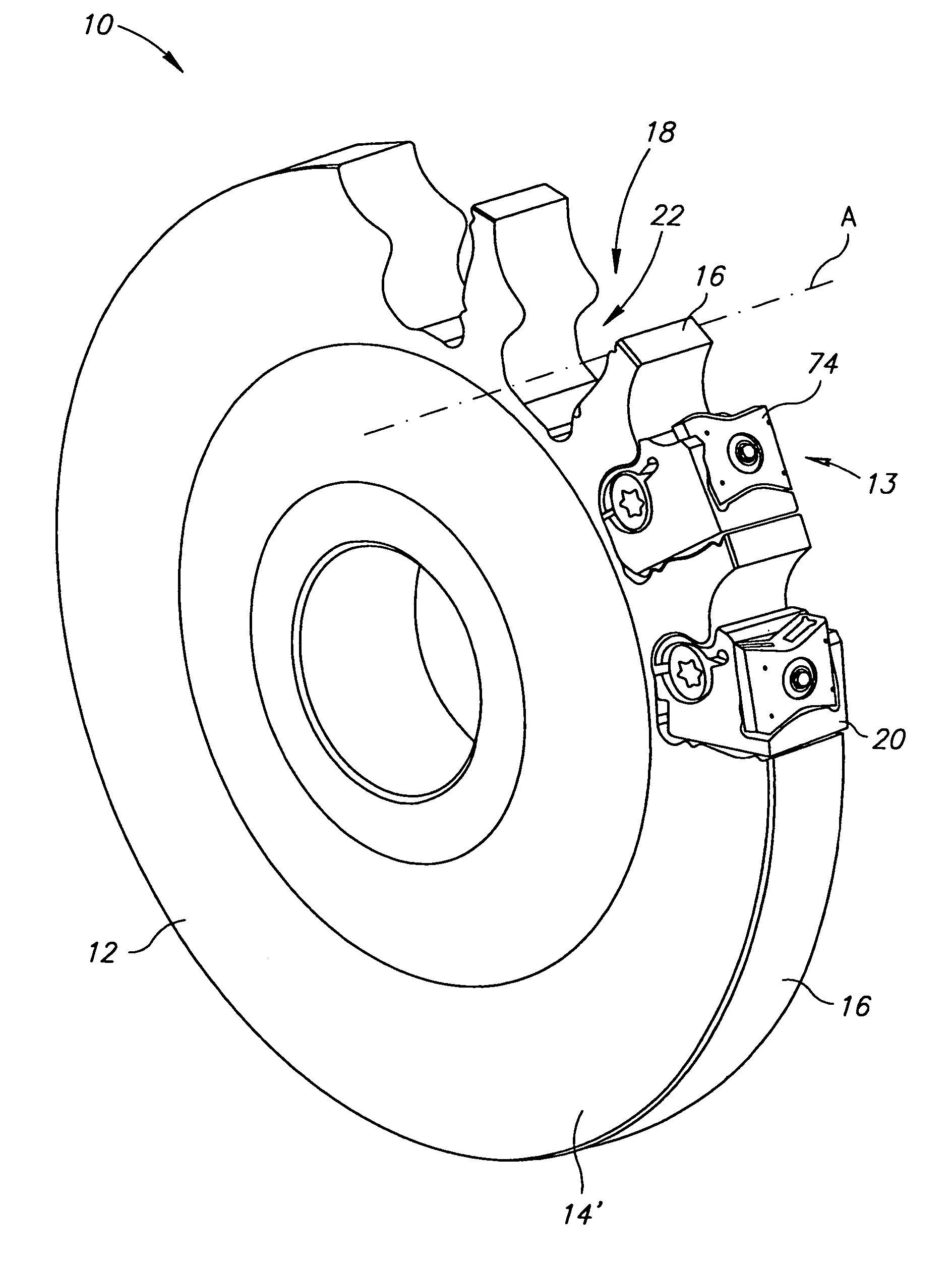
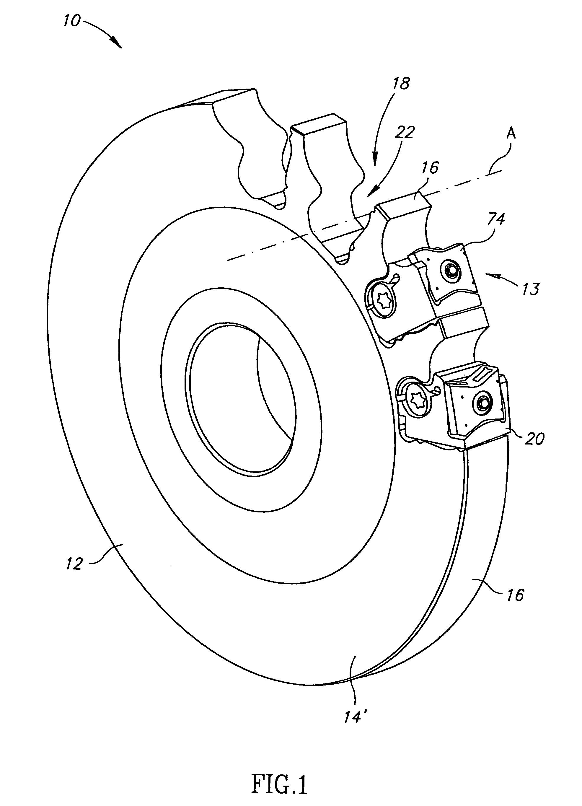
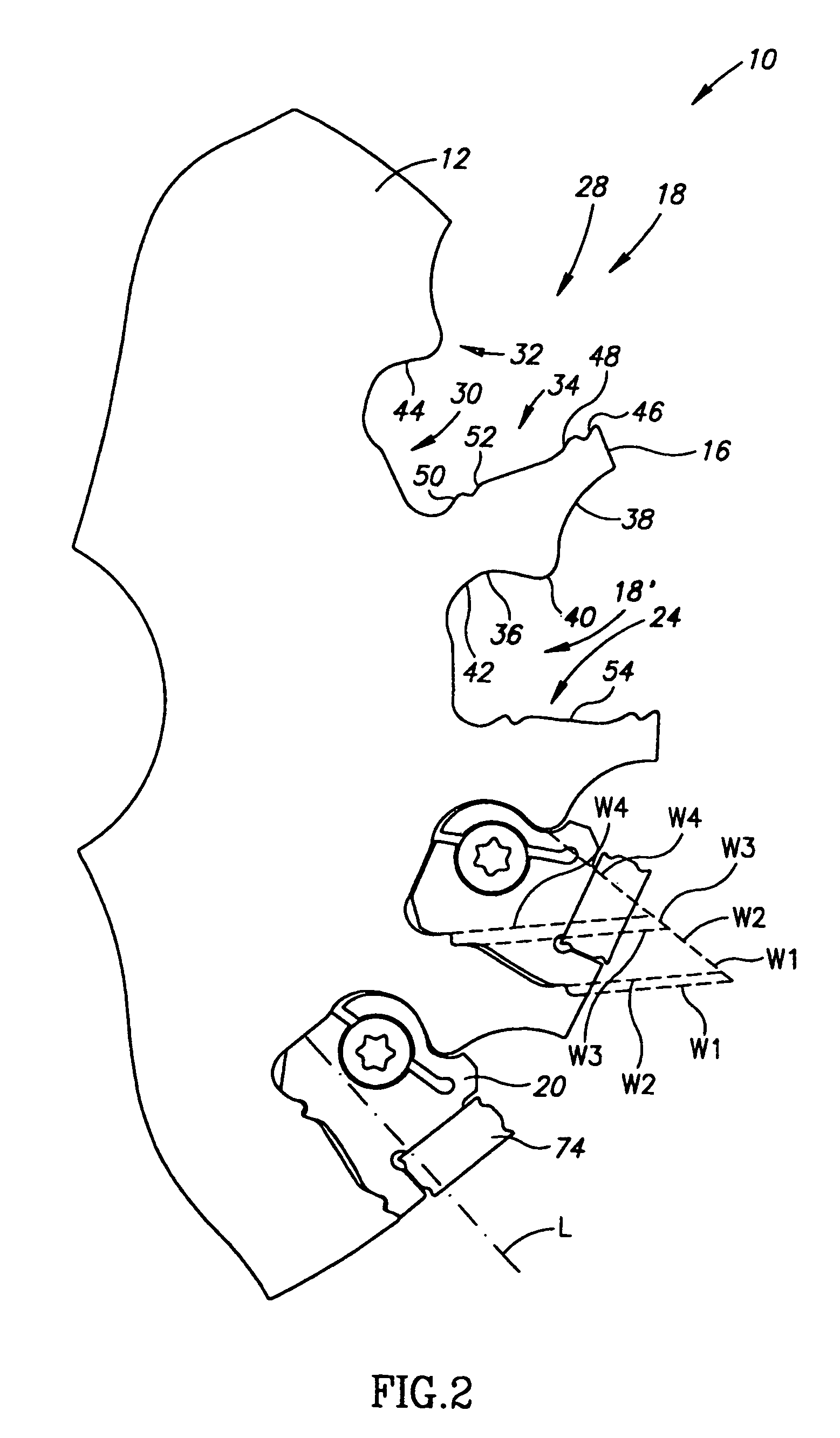
[0039]Attention is drawn to the drawings in which FIGS. 1 to 3 show a cutting tool 10 in accordance with the present invention. The particular cutting tool chosen to illustrate the invention is a disc-shaped milling cutter comprising a tool body 12 having two generally parallel end surfaces 14′, 14″ (end surface 14″ is on the hidden side of the tool body 12 and therefore not seen in the drawings) and a circumferential side surface 16 extending between the end surfaces 14′, 14″. The tool body 12 is provided with a plurality of circumferentially spaced apart cutting portions 13, each cutting portion 13 comprising a cartridge pocket 18 with an insert-bearing cartridge 20 retained therein.

[0040]Reference is now also made to FIGS. 4 to 8. Each cartridge pocket 18 is formed by a through going cutout 22, or groove, in the tool body 12, constituting an open ended housing having a generally concave inner surface 24 bounded by two substantially equally shaped opposing side openings 26′, 26″ f...


PUM

PropertyMeasurementUnit
lateral displacementaaaaaaaaaa
diametersaaaaaaaaaa
diameteraaaaaaaaaa

Abstract

A. cutting tool for metal cutting operations employing detachable cutting insert secured to cartridges. The cartridges have a clamping portion that is resiliently transformable between a normally non-expanded state and a biased expanded state by means of a clamping screw received in a through bore in the cartridge. The clamping portion is slidably insertable into the cartridge pocket when in the normally non-expanded state, and is securely retained in the cartridge pocket when in the biased expanded state.

Description

FIELD OF THE INVENTION[0001]The present invention relates to a cutting tool for machining metal workpieces, and more particularly to a rotary cutting tool having replaceable cutting inserts secured to a cartridge mounted in the tool body.BACKGROUND OF THE INVENTION[0002]Conventional cutting tools having cutting insert bearing cartridges, employ various means for securing the cartridge to the cutting tool body. In some cutting tools threaded bores are provided in the cutting tool body and corresponding through bores are provided in the cartridges. The cartridges are then secured to the cutting tool body by means of screws. Not only do threaded bores in the tool body require various metal cutting operations to produce them, or operations, but the mere presence of threaded bores can weaken the tool body. Furthermore, in the event of damage to the cutting tool, a broken off part of the screw can become lodged in the threaded bore. In other cutting tools, combinations of wedges and screw...

Claims


Application Information

Patent Timeline
Patent Type & Authority Patents(United States)
IPC IPC(8): B23C5/08B23C5/24
CPCB23C5/08B23C5/241B23B2205/02Y10T407/1932Y10T407/2288Y10T407/227B23C2200/367B23C5/24B23C5/2226B23C5/2204B23C2210/161
Inventor SATRAN, AMIRQEYS, TALAL
Owner ISCAR LTD
Why Eureka
Try Eureka