
Mounting device for mounting expansion cards in computer enclosure

a technology for mounting devices and expansion cards, which is applied in the direction of coupling device connections, electrical apparatus casings/cabinets/drawers, instruments, etc., can solve the problems of increasing the inconvenience of installation/removal process, time-consuming and cumbersome screw installation one by one, and difficult retrieval problems, so as to facilitate the installation and convenient effect of series attachmen

Inactive Publication Date: 2005-12-06
HON HAI PRECISION IND CO LTD
View PDF11 Cites 25 Cited by
  • Summary
  • Abstract
  • Description
  • Claims
  • Application Information

AI Technical Summary

Benefits of technology

The solution enables convenient and secure attachment and detachment of expansion cards, ensuring stability across different heights and reducing installation / removal complexity, while preventing accidental dislodging due to shock or vibration.

Problems solved by technology

However, installing screws one by one is time-consuming and cumbersome.
Moreover, during installation / removal of the expansion cards, one or more of the screws can easily fall into the crowded interior of the computer, thereby creating a difficult retrieval problem.
However, said other end of the locking bar is secured to the rear panel by a fixing screw which increases inconvenience in installation / removal process.
Additionally, because the locking bar is flat and slim, and the series of cover plates might be on different heights, the locking bar will fail to press on the cover plates which are on a lower position.
Therefore, the untouched, lower positioned cover plates might not be securely attached to the rear panel.
When suffered from shock or vibration, the cover plates will easily break away from the rear panel.

Method used


Image

  • Mounting device for mounting expansion cards in computer enclosure
  • Mounting device for mounting expansion cards in computer enclosure
  • Mounting device for mounting expansion cards in computer enclosure

Examples


Embodiment Construction

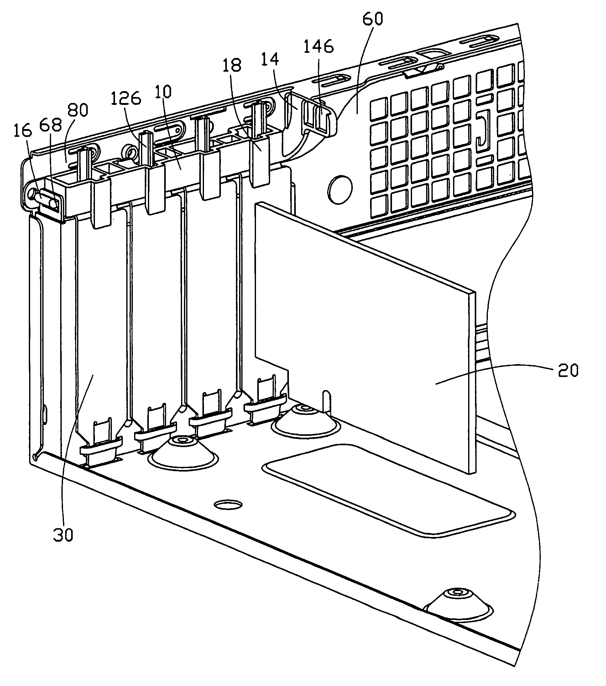
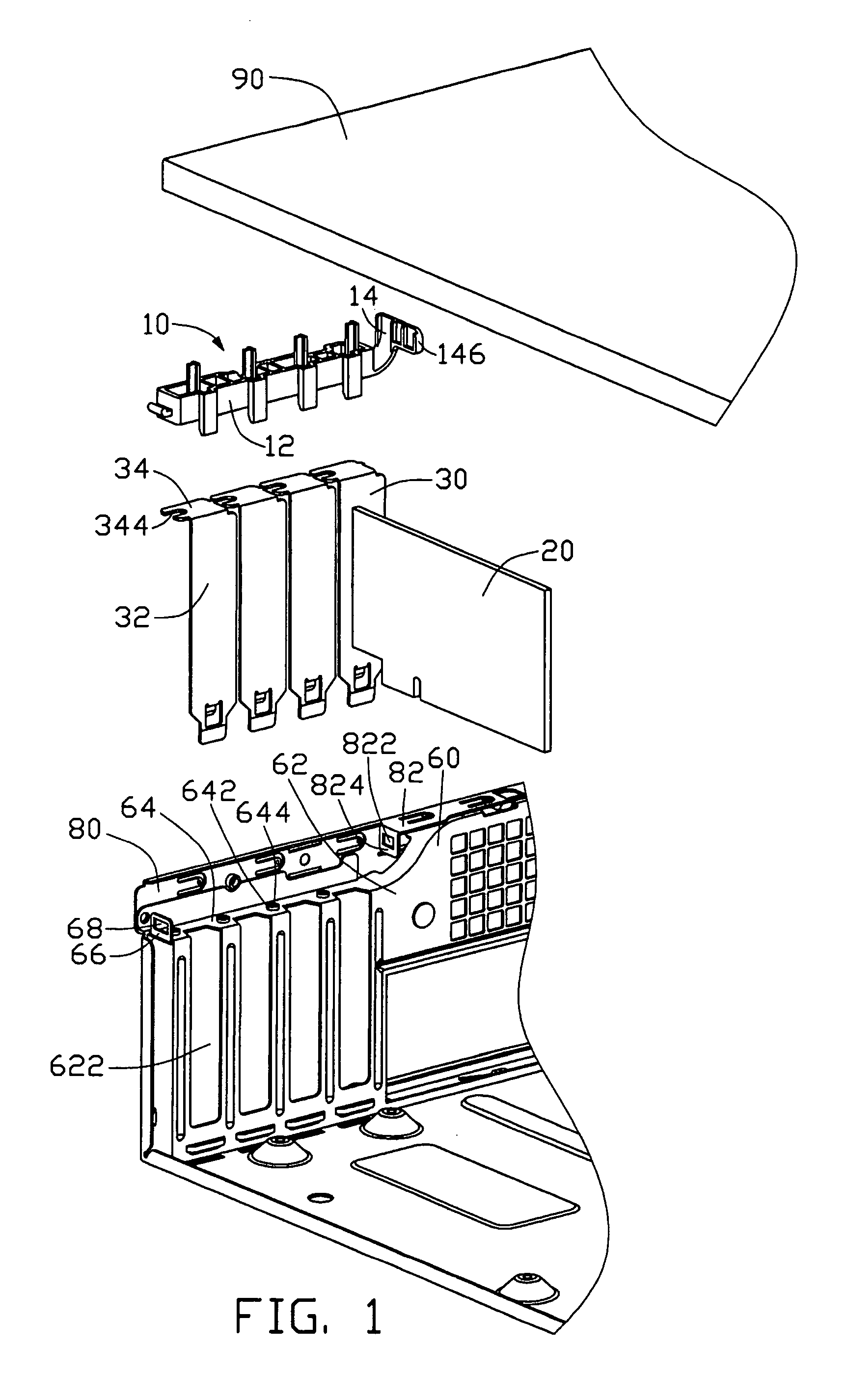
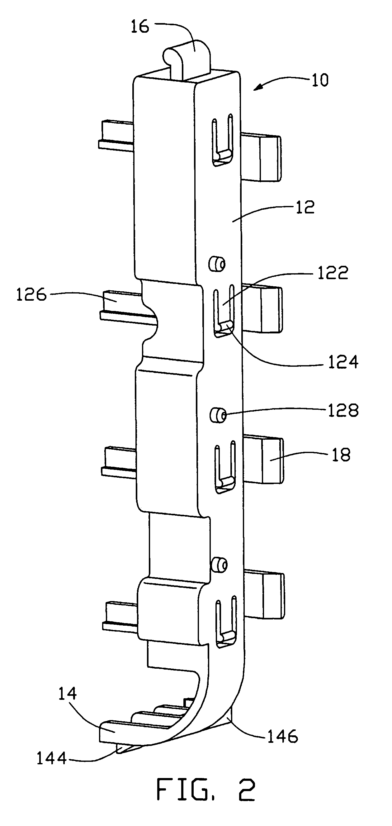
[0016]Referring to FIGS. 1–3, a mounting device 10 in accordance with the preferred embodiment of the present invention is used to fix a plurality of expansion cards 20 with cover plates 30 to an inturned card cage 60 which is attached to a rear panel 80 of a computer enclosure. Each cover plate 30 comprises a rectangular elongated portion 32 connected to the expansion card 20, and a bent portion 34 extending perpendicularly from one end of the elongated portion 32. A cutout 344 is defined in the bent portion 34.

[0017]The card cage 60 comprises a base wall 62, and a bent wall 64 extending perpendicularly from the base wall 62. A plurality of expansion card slots 622 is defined in the base wall 62 parallel to each other, and further extends to the bent wall 64, having a similar profile with the cover plates 30. A flange 82 is bent perpendicularly from an edge of the rear panel 80. A locking tab 824 extends perpendicularly from the flange 82 towards the bent wall 64 of the card cage 6...


PUM


Abstract

A mounting device (10) is for mounting expansion cards with cover plates (30) to a card cage (60) of a rear panel (80). Each cover plate includes an elongated portion (32) and a bent portion (34). The mounting device includes an elongated main body (12) with one end pivotally attached to the card cage, and the other end locked to the rear panel. A plurality of resilient fingers (122) is formed at an inner face of the main body for pressing the bent portions of the cover plate. A flexible pressing post (126) extends outwardly from a free end of each finger. A cover panel (90) is attached to the rear panel and presses the pressing posts to further secure the cover plates.

Description

BACKGROUND OF THE INVENTION[0001]1. Field of the Invention[0002]The present invention relates to a mounting device for mounting expansion cards in a computer enclosure, and particularly to a mounting device which readily secures a plurality of expansion cards in a computer enclosure and allows convenient removal of the expansion cards therefrom.[0003]2. Description of the Related Art[0004]In order to upgrade the operating capabilities of a personal computer, a plurality of expansion cards is operatively installed in the computer enclosure. Typical types of expansion cards include network cards, sound cards, graphics accelerator cards and multi-media cards, etc. These expansion cards may be installed in the computer enclosure during its original manufacture or by the computer purchaser.[0005]U.S. Pat. No. 4,745,524 discloses a plurality of mounting systems for mounting a plurality of expansion cards inside a computer chassis. Each mounting system includes a pressing element and a scr...

Claims


Application Information

Patent Timeline
Patent Type & Authority Patents(United States)
IPC IPC(8): G06F1/16G06F1/18H02G3/08H05K5/00H05K7/00H05K7/14
CPCG06F1/184G06F1/185G06F1/186H05K7/1408
Inventor WANG, WEN-TANGCHENG, CHENG-LUNGZHANG, JUN-XIONG
Owner HON HAI PRECISION IND CO LTD
Learn More