Fluid treatment system with UV sensor and intelligent driver

a technology of intelligent driver and treatment system, which is applied in the direction of water/sewage treatment by degassing, x-ray tube, optical radiation measurement, etc., can solve the problems of reducing the uv output of the emitter, unnecessary electricity usage, and shortening the life of the uv emitter

Inactive Publication Date: 2005-12-06
DANAHER GENERAL PARTNER COMPANY INC AS MANAGING PARTNER FOR VIQUA
View PDF35 Cites 43 Cited by
  • Summary
  • Abstract
  • Description
  • Claims
  • Application Information

AI Technical Summary

Benefits of technology

[0012]It is an object of the present invention to obviate or mitigate at least one disadvantage of previous UV fluid treatment systems. Generally, the present invention provides a fluid treatment system with a UV sensor and intelligent driver / controller.

Problems solved by technology

The main problem, particularly with the smaller UV treatment systems, is that although they may include a sensor to detect the UV level, they do not incorporate any means to detect water flow, forcing these systems to operate under assumed conditions of continuous maximum flow-rate.
Hence, the inability to detect flow conditions leads to undesirable heating of the water, unnecessary electricity usage, reduction of the emitter's UV output, and possible shortening of the UV emitter's life due to overheating.
To further exacerbate the above problem, traditional water flow sensors are either too costly, as in the case of magnetic flux flow sensors, for the purchasers of small systems or are unreliable, as in the case of paddlewheel flow-meters which can become stuck and hence fail to indicate flow altogether.
Another problem with conventional products is that even if an external flow sensor is incorporated, the additional devices required to receive, process, respond to, and display this signal are prohibitively expensive and technically complicated for the purchasers of small systems.
Further, conventional drivers for powering the UV emitters, do not have the capability to display detailed information pertaining to the fluid treatment parameters and diagnostic information pertaining to the system operation.
Typically, the information is limited to what can be displayed by indicator lights.
Unfortunately, dedicated UVT monitoring devices are costly and require connection to an additional controller if the system is to respond to the varying UVT.
In many applications, these devices are not included due to their cost and complexity.
Conversely, if the assumed UVT value is higher than actual, the system may deliver inadequate UV dose.

Method used


Image

  • Fluid treatment system with UV sensor and intelligent driver
  • Fluid treatment system with UV sensor and intelligent driver
  • Fluid treatment system with UV sensor and intelligent driver

Examples


Embodiment Construction

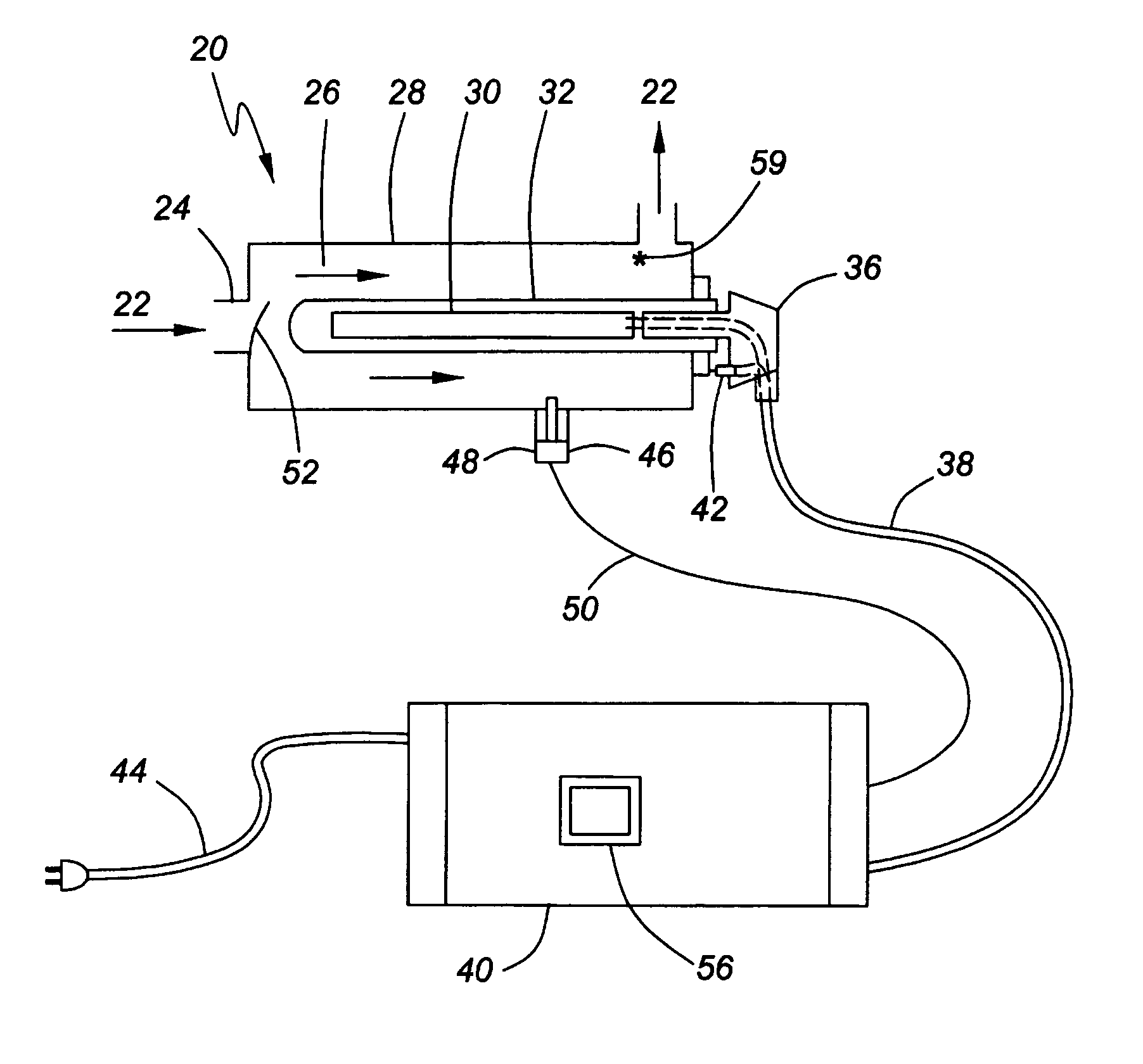
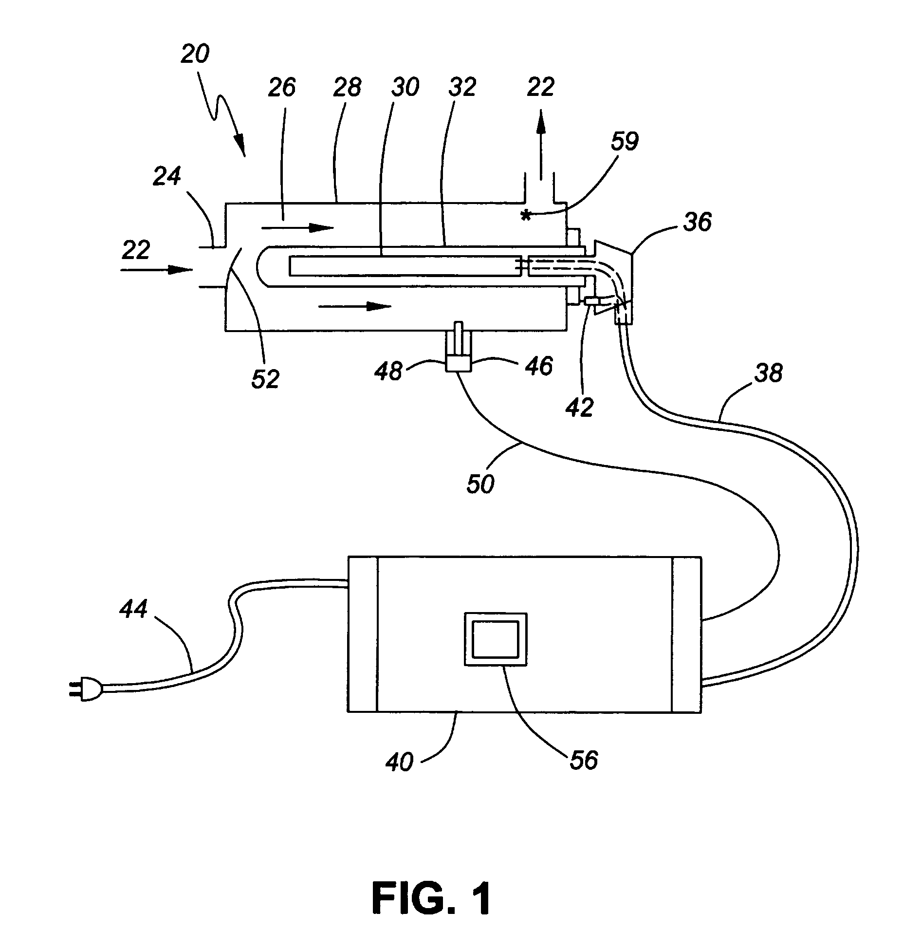
[0041]Generally, the present invention provides a fluid treatment system with UV sensor and intelligent driver / controller. More specifically, the present invention relates to a UV sensor with novel fluid flow detection capabilities that provides signals for multiple fluid-treatment parameters, for example UV intensity and fluid flow. Further, an intelligent ballast, or driver, or controller, as part of the fluid treatment system, has the novel capability of receiving, processing, responding to, and displaying of one or more parameters based on one or more input signals. The UV fluid treatment system is preferably for small enterprise and consumer use. The system includes a fluid treatment zone having a fluid inlet and a fluid outlet. A UV emitter and a sensor unit are disposed within the fluid treatment zone. The sensor unit includes multiple sensing means, such as fluid flow sensing means to sense fluid flow within the fluid treatment zone and UV sensing means to sense UV light lev...


PUM

PropertyMeasurementUnit
voltageaaaaaaaaaa
voltageaaaaaaaaaa
flow rateaaaaaaaaaa

Abstract

A fluid treatment system in which the fluid to be treated is irradiated with ultraviolet light (UV). The system includes a sensor with capabilities for detecting multiple fluid treatment parameters, such as UV intensity level and fluid flow. The sensor contains a combination of a UV sensing means such as a photodiode, a flow sensing means such as a vibration sensitive microphone, and associated electronics for processing and transmitting data pertaining to the fluid treatment parameters. The system can also include or alternatively include an intelligent driver that powers a UV lamp and has the novel capabilities to receive, process, respond to, and display multiple fluid treatment parameter signals from one or more sensors without the need for additional signal processing and/or control devices. Specifically, in a preferred embodiment, the power being delivered to the UV lamp will be adjusted as warranted by the intelligent driver's analysis of at least one fluid treatment parameter, such as flow condition.

Description

CROSS-REFERENCE TO RELATED APPLICATIONS[0001]This application claims the benefit of priority from U.S. Provisional Application No. 60 / 413,554, filed Sep. 26, 2002, the entire contents of which are incorporated herein by reference.FIELD OF THE INVENTION[0002]The present invention generally relates to fluid treatment systems that utilize ultraviolet light (UV), typically requiring an electrical ballast or driver to operate a UV emitter, a defined fluid treatment zone, and can include means to detect the level of UV within the fluid treatment zone.BACKGROUND OF THE INVENTION[0003]Existing products commonly found in the market-place include air and water treatment devices utilizing ultraviolet light as a means to inactivate, convert, or destroy some portion of undesirable contaminant that may be present in the fluid, which can be gas or liquid. For example, treatment devices using UV to inactivate pathogenic micro-organisms in water are commonplace and well established in the art. Such ...

Claims


Application Information

Patent Timeline
Patent Type & Authority Patents(United States)
IPC IPC(8): A61L2/10A61L2/28A61L9/20C02F1/00C02F1/32G01N21/33G06F13/10H01J61/20H05B41/36
CPCA61L2/10A61L9/20C02F1/325G01N21/33C02F2201/326C02F2209/006C02F2209/40
Inventor SCHAIBLE, UWE D.LEATHERLAND, STEVEN M.MENNEN, WILLIAM T.CAZZOLA, ROBERT J.
Owner DANAHER GENERAL PARTNER COMPANY INC AS MANAGING PARTNER FOR VIQUA
Why Eureka
Try Eureka