Unlock instant, AI-driven research and patent intelligence for your innovation.

Recording medium, method and apparatus for reproducing, and method and apparatus for recording

Inactive Publication Date: 2005-12-06
PANASONIC CORP
View PDF4 Cites 11 Cited by
  • Summary
  • Abstract
  • Description
  • Claims
  • Application Information

AI Technical Summary

Problems solved by technology

However, in the case where the irradiation power capable of reproducing data from the second recording layer 2105 is preset, when a focusing operation of a servo means or a tracking operation of the servo means is erroneously performed on the first recording layer 2013, there is a risk that data recorded on the first recording layer 2013 might be erased due to the excessively large irradiation power.
On the contrary, in the case of setting the irradiation power sufficiently small as to reproduce data from the first recording layer 2013, when the address information cannot be reproduced, there is a risk in determining that the servo means is performing an operation on the second recording layer 2105 and immediately increasing the irradiation power.
Further, it is not possible to securely discriminate between the first and second recording layers 2013 and 2015 by observing a focus error signal or a focus sum signal in which two elemental signals included in the focus error signal.

Method used


Image

  • Recording medium, method and apparatus for reproducing, and method and apparatus for recording
  • Recording medium, method and apparatus for reproducing, and method and apparatus for recording
  • Recording medium, method and apparatus for reproducing, and method and apparatus for recording

Examples


embodiment 1

(Embodiment 1)

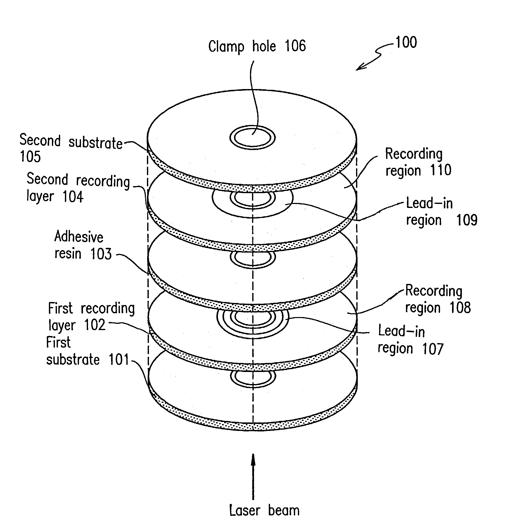
[0073]FIG. 1 is a structural diagram of an optical disk 100 according to Embodiment 1 of the present invention. In FIG. 1, the optical disk 100 includes a first substrate 101, a first recording layer 102, an adhesive resin 103, a second recording layer 104 and a second substrate 105. The first substrate 101, the first recording layer 102, the adhesive resin 103, the second recording layer 104 and the second substrate 105 have their respective clamp holes 106. The first recording layer 102 includes a lead-in region 107 and a recording region 108. The second recording layer 104 includes a lead-in region 109 and a recording region 110. The first and second substrates 101 and 105 are formed of a polycarbonate resin or the like and respectively protect the first and second recording layers 102 and 104.

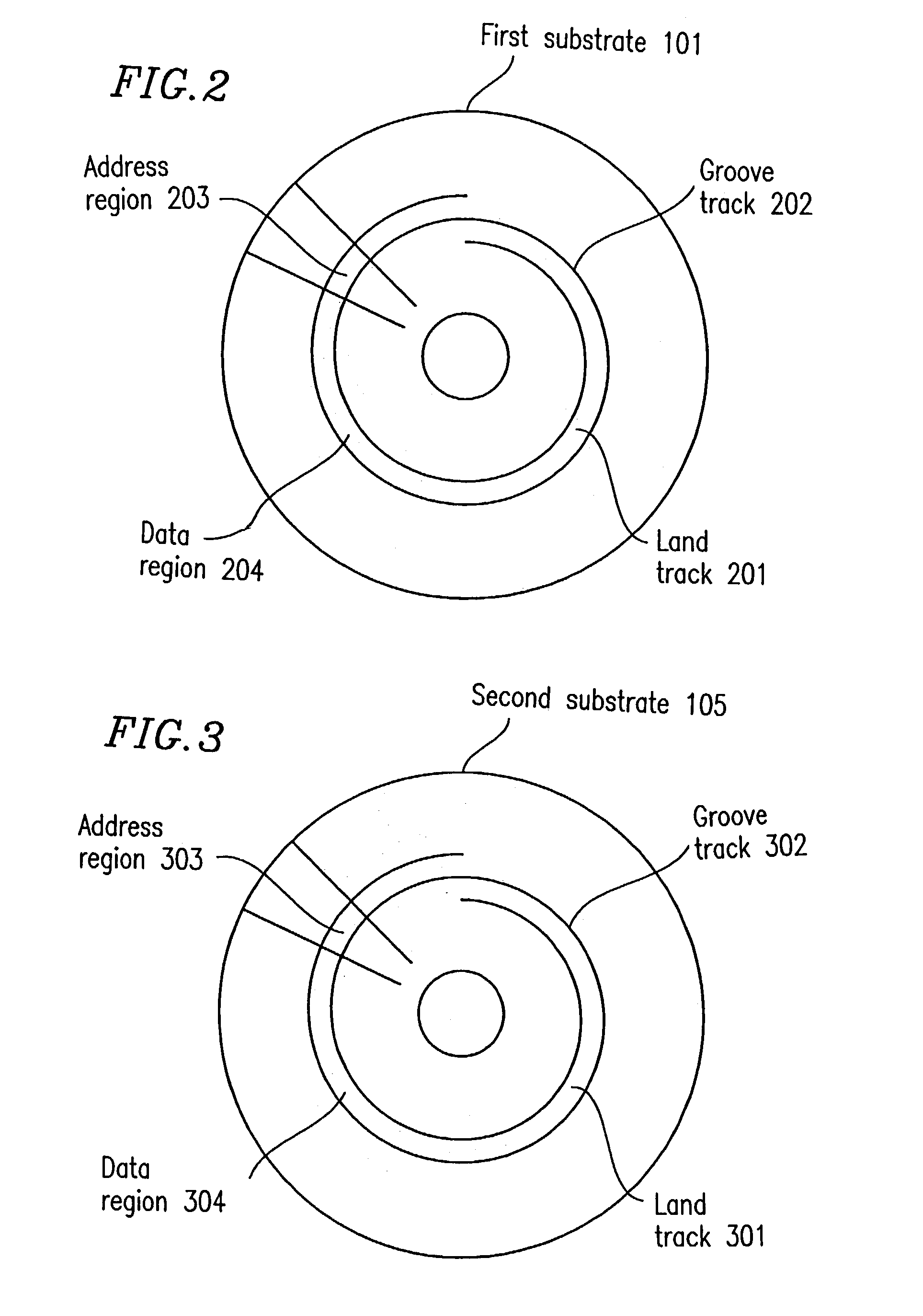
[0074]Next, FIG. 2 is referenced. FIG. 2 illustrates a sector structure on the first substrate 101 included in the optical disk 100 shown in FIG. 1. The first substrate 101 is...

embodiment 2

(Embodiment 2)

[0122]FIG. 16 is a structural diagram of an optical disk 1500 according to Embodiment 2 of the present invention. In FIG. 16, the optical disk 1500 includes a first substrate 901, a first recording layer 902, an adhesive resin 903, a second recording layer 904 and a second substrate 905. The first substrate 901, the first recording layer 902, the adhesive resin 903, the second recording layer 904 and the second substrate 905 have their respective clamp holes 906. The first recording layer 902 includes a lead-in region 907 and a recording region 908. The second recording layer 904 includes a lead-in region 909 and a recording region 910. The first and second substrates 901 and 905 are formed of a polycarbonate resin or the like and respectively protect the first and second recording layers 902 and 904.

[0123]Next, FIG. 17 is referenced. FIG. 17 illustrates a sector structure on the first substrate 901 included in the optical disk 1500 shown in FIG. 16. The first substrat...


PUM


Abstract

In a recording medium which is circular and has first and second recording layers, the first and second recording layers each include one or more first tracks extending concentrically or spirally and one or more second tracks extending concentrically or spirally, each of the one or more first tracks and the one or more second tracks includes a plurality of first sectors and a plurality of second sectors, each of the plurality of first sectors includes first and second regions, each of the plurality of second sectors includes third and fourth regions, first and second grooves are formed in each of the second and fourth regions, the first and second grooves extending concentrically or spirally and oscillating sinusoidally, oscillation of the first groove has a first oscillation characteristic at a first prescribed position in the second region, oscillation of the second groove has a second oscillation characteristic at a second prescribed position in the fourth region, and the first and second oscillation characteristics are different from each other.

Description

TECHNICAL FIELD[0001]The present invention relates to a recording medium on / from which information is recorded / reproduced when irradiated with a light beam, and particularly to a multilayered optical disk having a plurality of laminated recording layers on / from which information is recorded / reproduced when irradiated with a light beam from a specific surface of the disk.BACKGROUND ART[0002]Recently, a variety of optical disks on / from which a large quantity of information can be recorded / reproduced have been developed. An example of large capacity optical disks is a double-sided optical disk in which two optical disk pieces are attached together and information can be recorded / reproduced on / from either side of the disk. However, in the field which frequently requires random access, for example, recording mediums for use with computers or game machines, there is a demand that the optical disk has a large recording capacity while any data in the disk can be accessed without turning the...

Claims


Application Information

Patent Timeline
IPC IPC(8): G11B7/00G11B7/0045G11B7/005G11B7/007G11B19/12
CPCG11B7/0045G11B7/005G11B7/007G11B7/00718G11B19/125G11B19/128G11B2007/0013
Inventor SHOJI, MAMORUNAKAMURA, ATSUSHIISHIDA, TAKASHIHISAKADO, YUJI
Owner PANASONIC CORP
Features
  • R&D
  • Intellectual Property
  • Life Sciences
  • Materials
  • Tech Scout
  • Unparalleled Data Quality
  • Higher Quality Content
  • 60% Fewer Hallucinations
Learn More