Electromagnetic flow meter having processing means resolving output data into a non-flow waveform component

a technology of output data and flow waveform, which is applied in the direction of volume flow measurement devices, liquid/fluent solid measurement, instruments, etc., can solve the problems of system performance often limited, system may exhibit errors at other operating conditions, and inhibit the ability to determine the flow in a static fashion

Inactive Publication Date: 2005-12-13
ABB LTD
View PDF12 Cites 9 Cited by
  • Summary
  • Abstract
  • Description
  • Claims
  • Application Information

AI Technical Summary

Benefits of technology

[0013]In this method, by taking the novel step of resolving into expected waveform components, rather than the conventional method of correlating each frequency component of the sampled output data with a sine wave, a number of advantages can be obtained. Although the shaped excitation waveform will effectively contain multiple frequency components, it has been found that it is not necessary to process each component separately to obtain a measure of flow.
[0048]The ability for the meter to provide a meaningful self-diagnosis may be very beneficial—a dynamic estimate of the meter accuracy may be provided. For example, it might be that under unfavourable conditions, the meter is only 1% accurate but under good signal conditions may be 0.05% accurate or better. The meter may determine a measure of accuracy, preferably based on the non-flow signal, and may report this with the measurement value. Downstream equipment may use the dynamically reported figure, rather than having to assume a worst case accuracy of 1%.

Problems solved by technology

This inhibits the ability to determine the flow in a static fashion.
While using some kind of alternating signal to excite the meter is usually necessary, it does introduce its own particular problem, namely that electromagnetic coupling between the coil current and the electrode wires typically creates a signal at the electrodes when there is no fluid flow through the conduit.
Performance of the system is often limited by the success of this zero removal system.
In many systems where the adjustment is only made at one operating condition (factory calibration) then the system may exhibit errors at other operating conditions, typically temperature or installation related.
Conversely, if a measurement is not taken sufficiently quickly, there is a potential problem of zero drift.
The “square wave” will not normally be true square wave as the slew rate will be limited by the apparatus and will often be deliberately limited to reduce effects of the high rate of change of current.

Method used


Image

  • Electromagnetic flow meter having processing means resolving output data into a non-flow waveform component
  • Electromagnetic flow meter having processing means resolving output data into a non-flow waveform component
  • Electromagnetic flow meter having processing means resolving output data into a non-flow waveform component

Examples


Embodiment Construction

[0010]The system and method described herein may provide a novel solution to at least some of the problems described above whereby a pulsed or square wave excitation can be used but the meter can be operated significantly faster than would normally be possible.

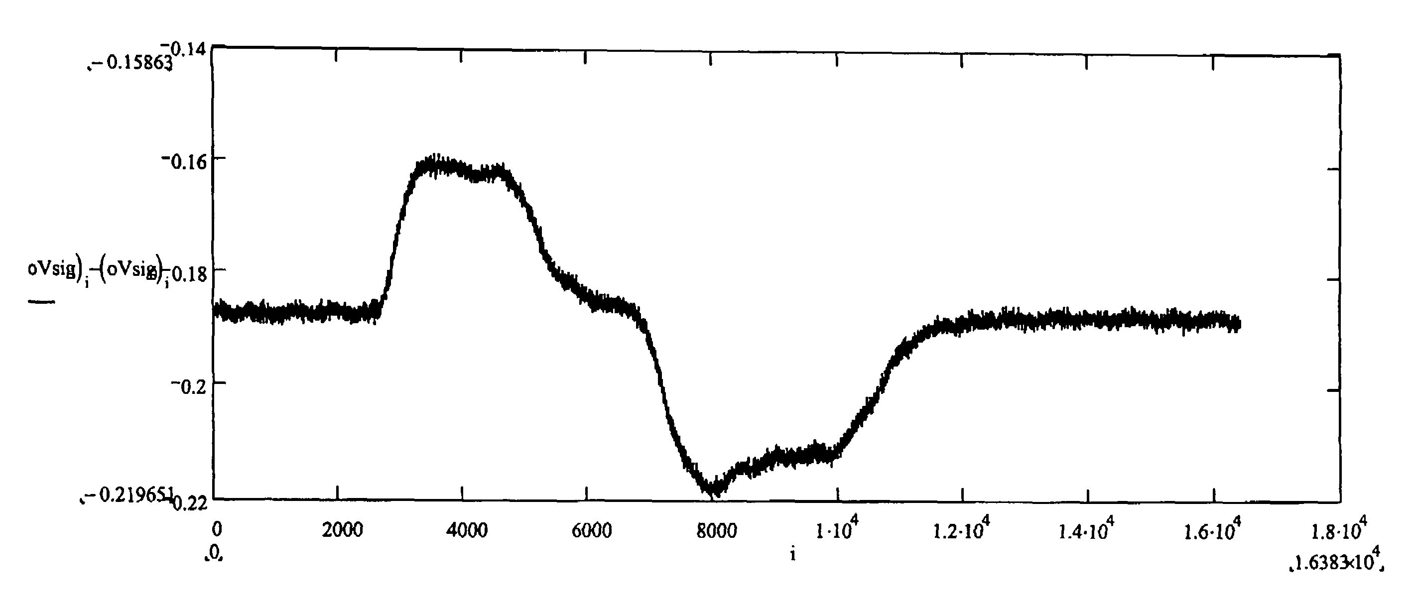
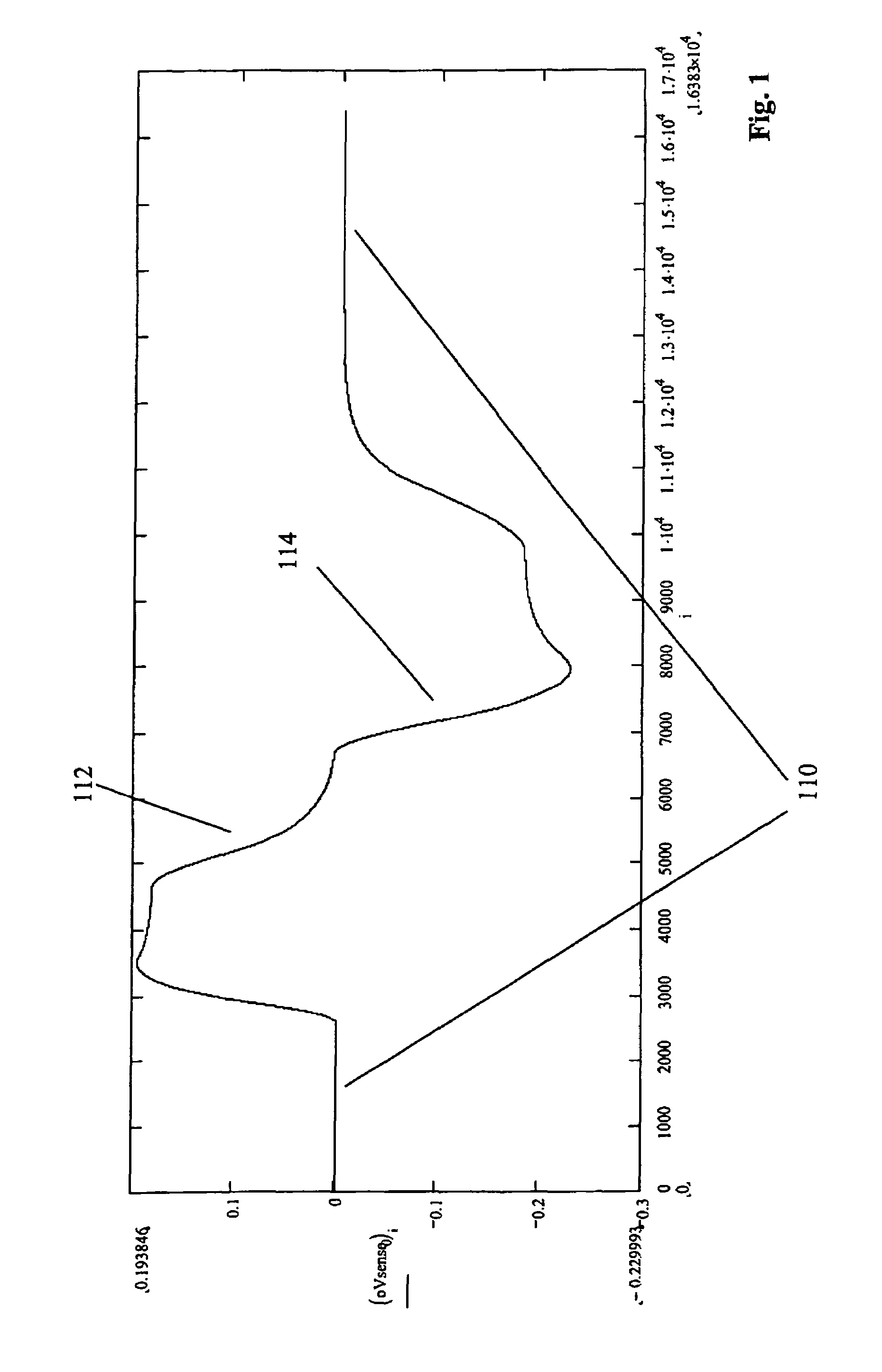
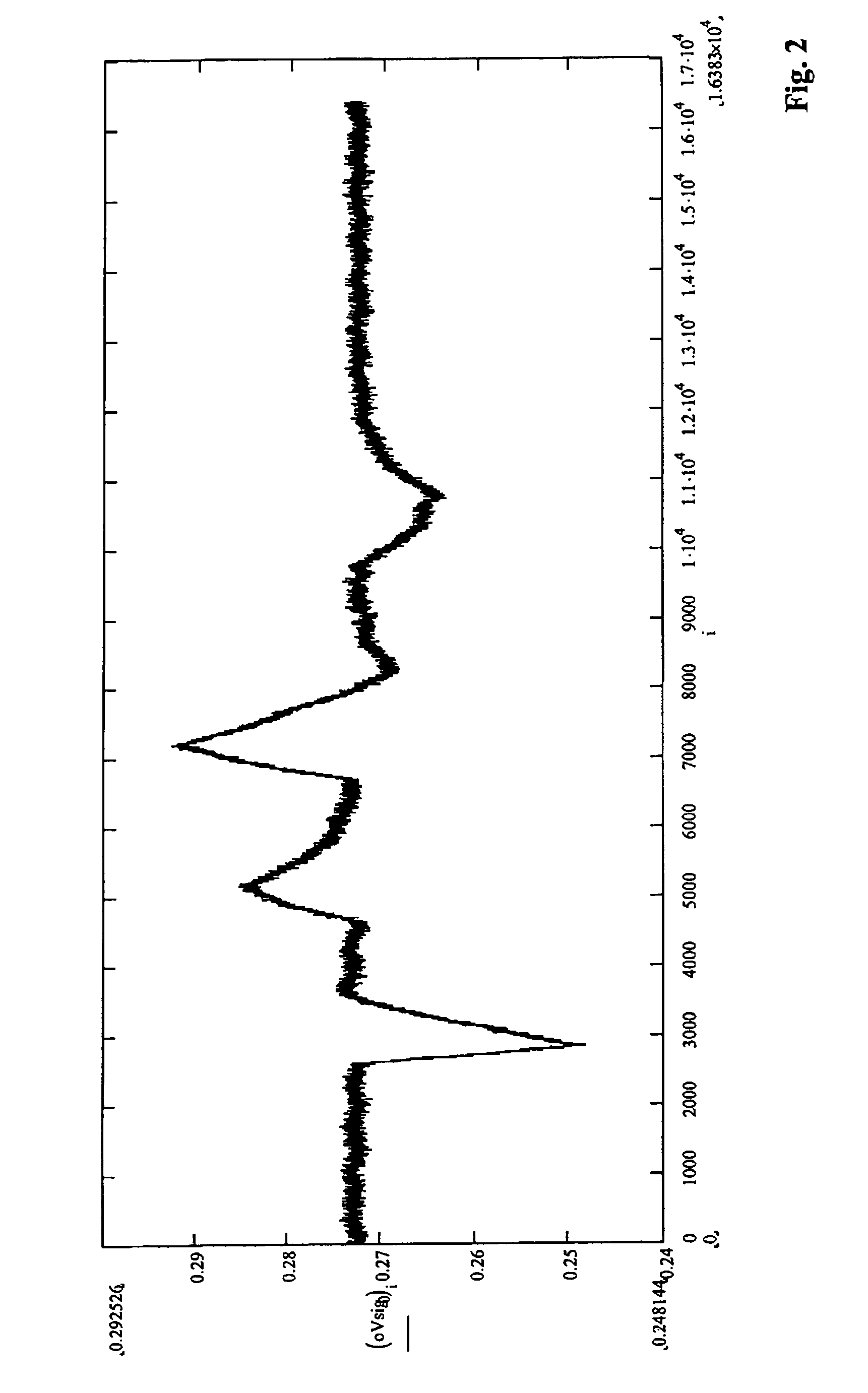
[0011]According to a first aspect the invention provides a method of obtaining a measure of flow from an electromagnetic flow meter comprising applying a shaped excitation waveform, receiving an output from the meter and resolving sampled output data from the meter into a non-flow waveform component and a flow waveform component to derive a measure of flow.

[0012]By shaped, we mean a waveform having a non-sinusoidal shape. The waveform can be considered as a shaped waveform comprising a plurality of frequency components, although the components may not be explicitly added as the signal may be directly generated in the time domain, for example using a Digital Signal Processor (DSP).

[0013]In this method, by taking the novel step ...


PUM


Abstract

A method of obtaining a measure of flow from an electromagnetic flow meter is disclosed. A shaped excitation waveform is applied to the flow meter and an output is received from the meter. The sampled output data from the meter is then resolved into a non-flow waveform component and a flow waveform component to derive a measure of flow. Resolving the data into expected waveform components rather than correlating each frequency component of the sampled output data with a sine wave may allow readings to be obtained without processing each frequency component separately. Also, the method may allow more accurate removal of the non-flow component from the output signal, and may decrease the time delay before the initial reading and allow the use of a greater reading repetition rate.

Description

CROSS-REFERENCE TO RELATED APPLICATIONS[0001]This application is related to U.S. patent application Ser. No. 10 / 817,765, filed on the same day as the present application, having the same inventor as the present application, and entitled “ELECTROMAGNETIC FLOW METER”. The disclosure of the above-described filed application is hereby incorporated by reference.BACKGROUND OF THE INVENTION[0002]The present invention relates to electromagnetic flow meters. However, aspects of signal processing techniques disclosed herein may be more broadly applied. The operating principles of Electromagnetic Flow Meters are well known, discussed for example in GB-A-2,380,798.[0003]Where the sensing electrodes are in contact with the fluid, due to electrochemical or other effects, a DC potential is usually present across the electrodes even when there is no coil excitation, i.e. no field. That component of the signal is independent of the flow and is generally not static. For example, it may drift randomly...

Claims


Application Information

Patent Timeline
Patent Type & Authority Patents(United States)
IPC IPC(8): G01F1/60
CPCG01F1/60
Inventor WRAY, TROY
Owner ABB LTD
Why Eureka
Try Eureka