One-piece reusable plastic fastener

a plastic fastener and one-piece technology, applied in the field of plastic fasteners, can solve the problems of difficult to remove from the substrate, correspondingly difficult to insert the fastener into the bore formed through the substrate, and difficult to withdraw, so as to achieve the effect of lowering the for

Inactive Publication Date: 2005-12-13
ILLINOIS TOOL WORKS INC
View PDF14 Cites 62 Cited by
  • Summary
  • Abstract
  • Description
  • Claims
  • Application Information

AI Technical Summary

Benefits of technology

[0007]A cored-out section formed into the central portion of the shank is deformed inwardly as the shank of the fastener is inserted into a bore formed through a panel. This deformation is created by inwardly directed forces applied to the flanges as the fastener is inserted into a bore in a substrate. The deformation of the cored-out section lowers the force required to insert the fastener into the bore formed through the substrate.

Problems solved by technology

An ideal plastic fastener can be inserted into a bore formed through a substrate relatively easy but is difficult to withdraw.
Unfortunately, one characteristic of plastic fasteners of this type is that because the fasteners themselves are fashioned of relatively flexible materials, fasteners that are easy to insert into a bore formed through a substrate tend to be relatively easy to remove from the substrate.
Similarly, where a fastener is difficult to remove from a substrate, it is generally correspondingly difficult to insert that fastener into the bore formed through the substrate.
Accordingly, there is a need for a reusable plastic fastener that may be easily inserted into a bore formed through a substrate, yet is difficult to remove from the substrate.
While the fastener described in the '055 patent performs admirably, the ratio of the force required to insert the fastener into a bore to the force required to withdraw the fastener from the bore is not ideal.

Method used


Image

  • One-piece reusable plastic fastener
  • One-piece reusable plastic fastener

Examples


Embodiment Construction

[0014]Although the disclosure hereof is detailed and exact to enable those skilled in the art to practice the invention, the physical embodiments herein disclosed merely exemplify the invention which may be embodied in other specific structure. While the preferred embodiment has been described, the details may be changed without departing from the invention, which is defined by the claims.

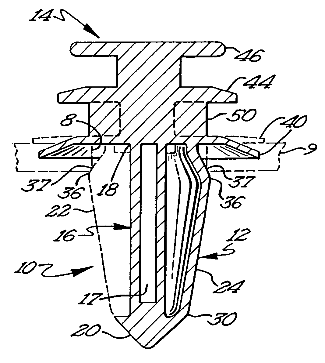
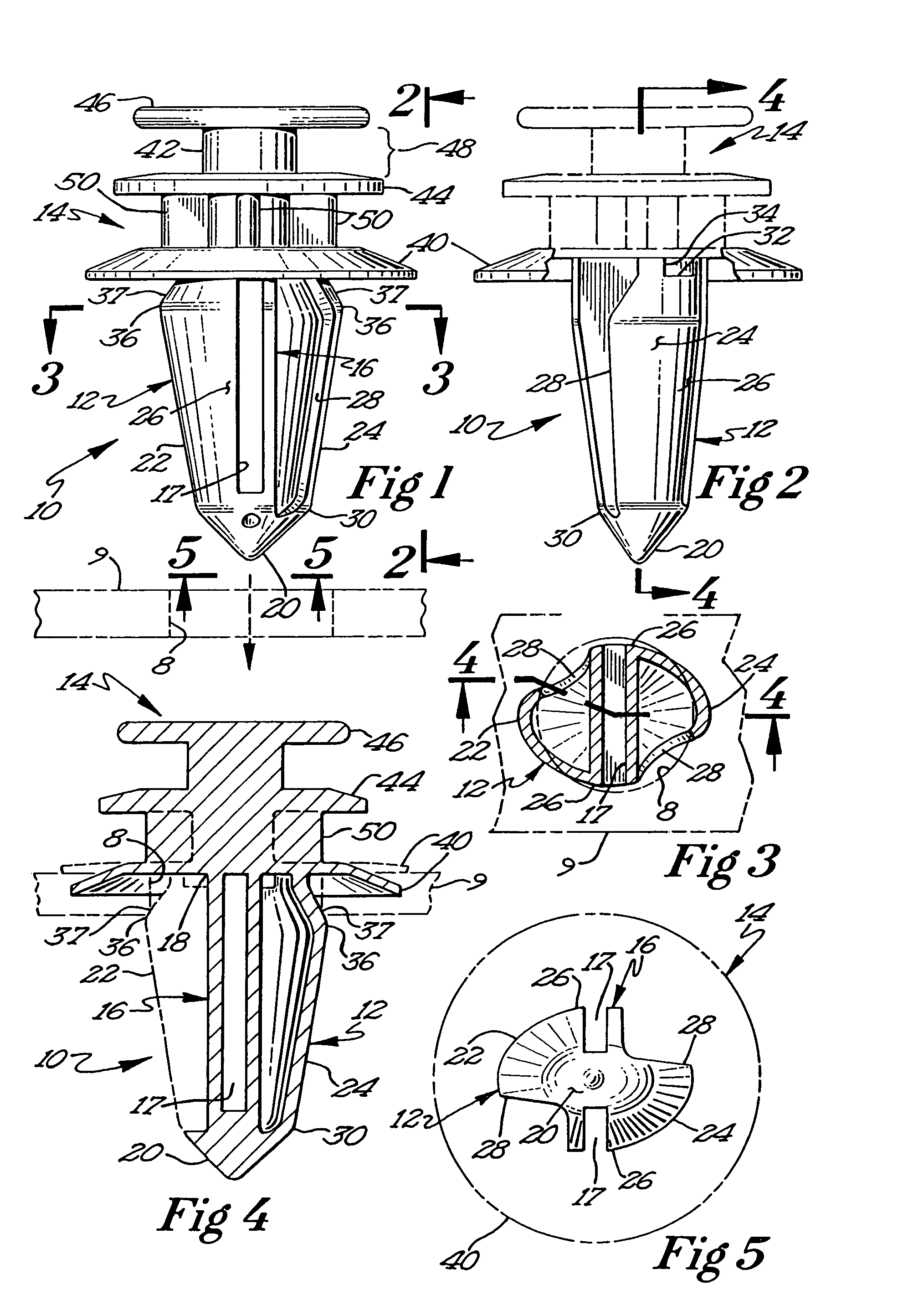
[0015]FIGS. 1 and 2 show a front and a side view, respectively, of a fastener 10 constructed and arranged according to the principals of the present invention. Fastener 10 generally comprises a shank 12 that extends downwardly and generally perpendicularly to a head 14. The head 14 of the fastener 10 is illustrated in FIG. 2 in phantom lines to indicate that the head 14 may take many configurations and is not limited to the preferred embodiment illustrated most clearly in FIG. 1.

[0016]The shank 12 of the fastener 10 has a central structure 16 that extends the entire length of the shank 12. At a bas...


PUM


Abstract

A reusable plastic fastener has an elongated shank having two flexible curved flanges secured thereto and a head secured to a central portion of the shank. The flanges are secured at a leading edge to the central portion and curve away to terminate in a trailing edge that is unsupported between a distal end and a base of the central portion. A top edge of each of the flanges is secured to the head of the fastener by a tab. The exterior of the flexible flanges extends outwardly away from the central portion beginning at the distal end of the central portion and is angled back in towards the central portion near the base of the central portion so as to form a shoulder between the flexible flanges and the head of the fastener. The central portion of the shank has at least one cored-out section.

Description

FIELD OF THE INVENTION[0001]The present invention relates to plastic fasteners for securing objects to a framework such as the sheet metal frame or body of an automobile.BACKGROUND OF THE INVENTION[0002]Plastic fasteners enjoy widespread use in the automotive industries and in other industries in applications where an object must be secured to a relatively thin substrate such as the sheet metal frame or body of an automobile. An ideal plastic fastener can be inserted into a bore formed through a substrate relatively easy but is difficult to withdraw.[0003]Unfortunately, one characteristic of plastic fasteners of this type is that because the fasteners themselves are fashioned of relatively flexible materials, fasteners that are easy to insert into a bore formed through a substrate tend to be relatively easy to remove from the substrate. Similarly, where a fastener is difficult to remove from a substrate, it is generally correspondingly difficult to insert that fastener into the bore...

Claims


Application Information

Patent Timeline
Patent Type & Authority Patents(United States)
IPC IPC(8): F16B21/08
CPCF16B21/086Y10T24/44026
Inventor HANSEN, WAYNE M.
Owner ILLINOIS TOOL WORKS INC
Why Eureka
Try Eureka