Clamp meter with dual display

a display and display technology, applied in the field of electronic test instruments, can solve the problems of difficult to read the display, if not impossible, etc., and achieve the effect of being easily visibl

Active Publication Date: 2005-12-13
IDEAL IND INC
View PDF26 Cites 29 Cited by
  • Summary
  • Abstract
  • Description
  • Claims
  • Application Information

AI Technical Summary

Problems solved by technology

This can make it difficult to read the display in certain situations.
Accordingly, when the clamp jaws are placed around a conductor the display can be forced into a position which may make reading the display difficult, if not impossible.

Method used


Image

  • Clamp meter with dual display
  • Clamp meter with dual display
  • Clamp meter with dual display

Examples


Embodiment Construction

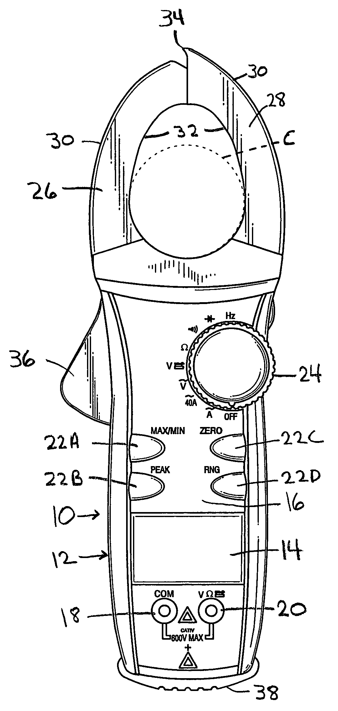
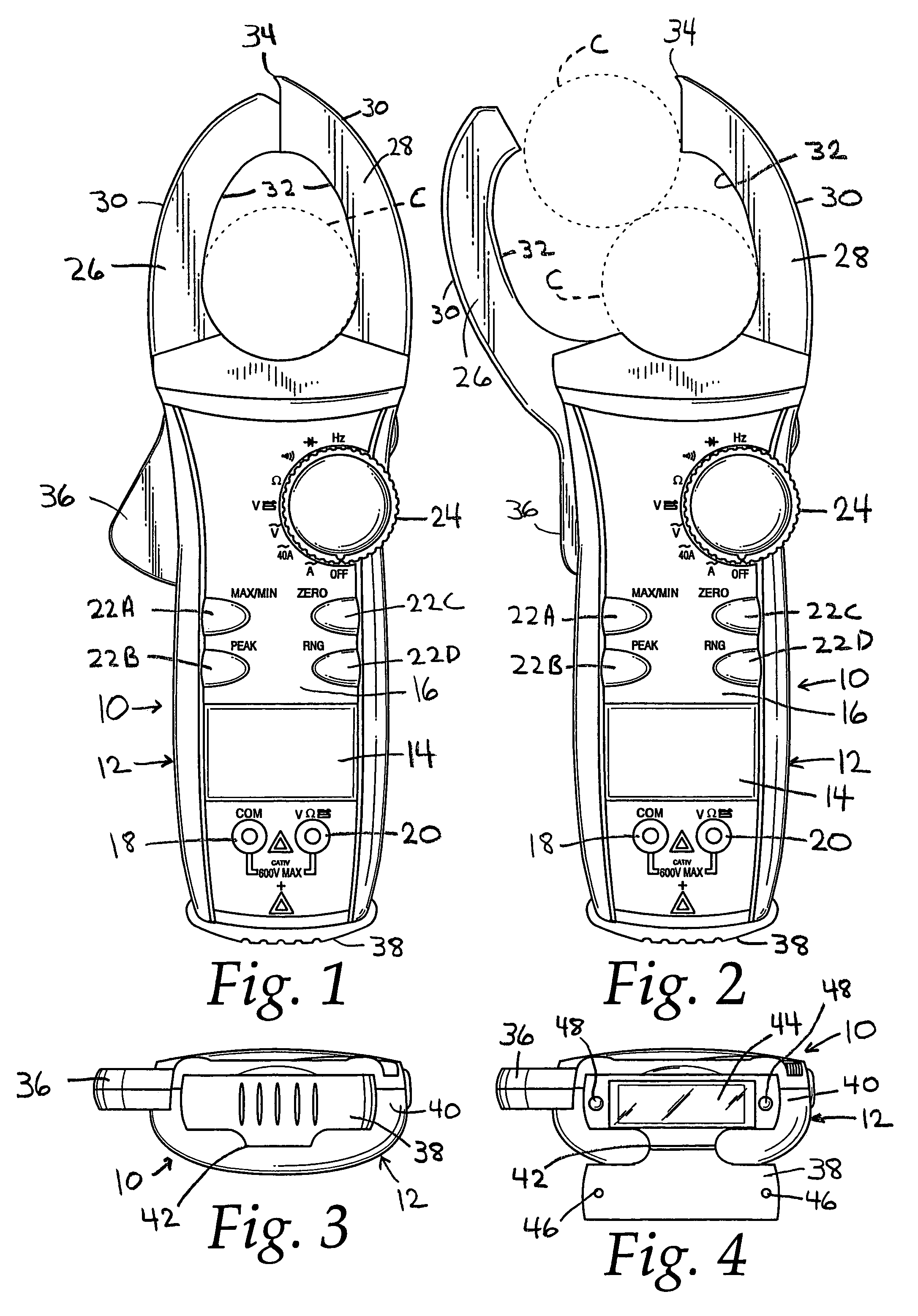
[0013]FIGS. 1–4 illustrate a clamp meter 10 according to the present invention. The clamp meter has an elongated housing 12 that mounts a first digital display 14. The display is mounted such that its outer surface is generally contiguous with the front face 16 of the housing. Two input jacks 18, 20 are provided for receiving test leads (not shown). The housing 12 is made from a hard, durable, lightweight plastic material. Also included on the front face 16 is a series of pushbuttons 22A–22D for selecting one or more of the testing functions of the meter. A selector knob or dial 24 is disposed on the front face 16 for choosing an electrical measurement mode.

[0014]Extending from the top of the housing is a pair of rigid clamp jaws 26, 28. Typically one of the jaws is pivotally mounted in the housing. In the embodiment shown jaw 26 is movable. Jaw 26 is spring-biased to a closed position against fixed jaw 28. The jaws 26, 28 have an arcuate shape to present outer convex surfaces 30 an...


PUM


Abstract

A clamp type digital multimeter has one or more digital displays mounted so as to permit at least one of the displays to be read even when attachment of the clamp jaws about a conductor forces the display into an orientation that renders it inaccessible. The meter either has a single display that can be pivoted to an orientation convenient for viewing, or it has dual displays mounted on separate surfaces of the meter's housing. A protective flap may cover one or both of the displays when it is not needed for viewing.

Description

BACKGROUND OF THE INVENTION[0001]This invention relates generally to electronic test instruments, particularly digital multimeters having a current sensing clamp. Digital multimeters, or DMM's, are used to measure a variety of electrical parameters, such as AC voltage, DC voltage, resistance and current. Clamp-type DMMs, also known simply as clamp meters, can measure current without interfering with the current carrying conductor. One such clamp meter is described in U.S. patent application Ser. No. 09 / 774,526, the disclosure of which is hereby incorporated by reference. In addition, clamp meters have the ability to measure fairly high levels of current.[0002]Clamp meters measure current flow in a conductor without having to make electrical connection with the conductors forming the circuit. Instead two clamp jaws having electrical coils embedded therein encircle the conductor and sense the magnetic field created by the current flow in order to measure the current. However, the phys...

Claims


Application Information

Patent Timeline
Patent Type & Authority Patents(United States)
IPC IPC(8): G01R1/04G01R1/22
CPCG01R1/22G01R1/04
Inventor GREGOREC, JR., JAMES L.
Owner IDEAL IND INC
Why Eureka
Try Eureka