Collision avoidance using limited range gated video

a technology of limited range and video, applied in closed circuit television systems, anti-collision systems, special data processing applications, etc., can solve the problems of low cost uav with collision avoidance, approach failure, and limiting factor of the accuracy with which objects may be located

Active Publication Date: 2005-12-13
ELBIT SYSTEMS OF AMERICA LLC
View PDF6 Cites 303 Cited by
  • Summary
  • Abstract
  • Description
  • Claims
  • Application Information

AI Technical Summary

Benefits of technology

[0009]To meet this and other needs, and in view of its purposes, the present invention provides a collision avoidance system for a vehicle having a collision avoidance processor, and an active sensor for obtaining successive range measurements to objects along a path transversed by the vehicle. The active sensor includes a near range gate for obta

Problems solved by technology

When attempting to traverse a space where obstacles prevent a straight-line path, the limiting factor becomes the accuracy with which objects may be located.
This approach fails, however, if the spatial separation between obstructions becomes less than the illum

Method used


Image

  • Collision avoidance using limited range gated video
  • Collision avoidance using limited range gated video
  • Collision avoidance using limited range gated video

Examples


Embodiment Construction

[0029]Objects in a scene may be placed in 2D space using spherical coordinates, theta and phi. In order to determine position in the third dimension, rho (or range) is also required. Extracting accurate range information using a range gated camera is problematic due to limitations of the illuminator, with cost tending to increase with increases in resolution. The higher the desired range accuracy, the shorter the required illuminator pulse width.

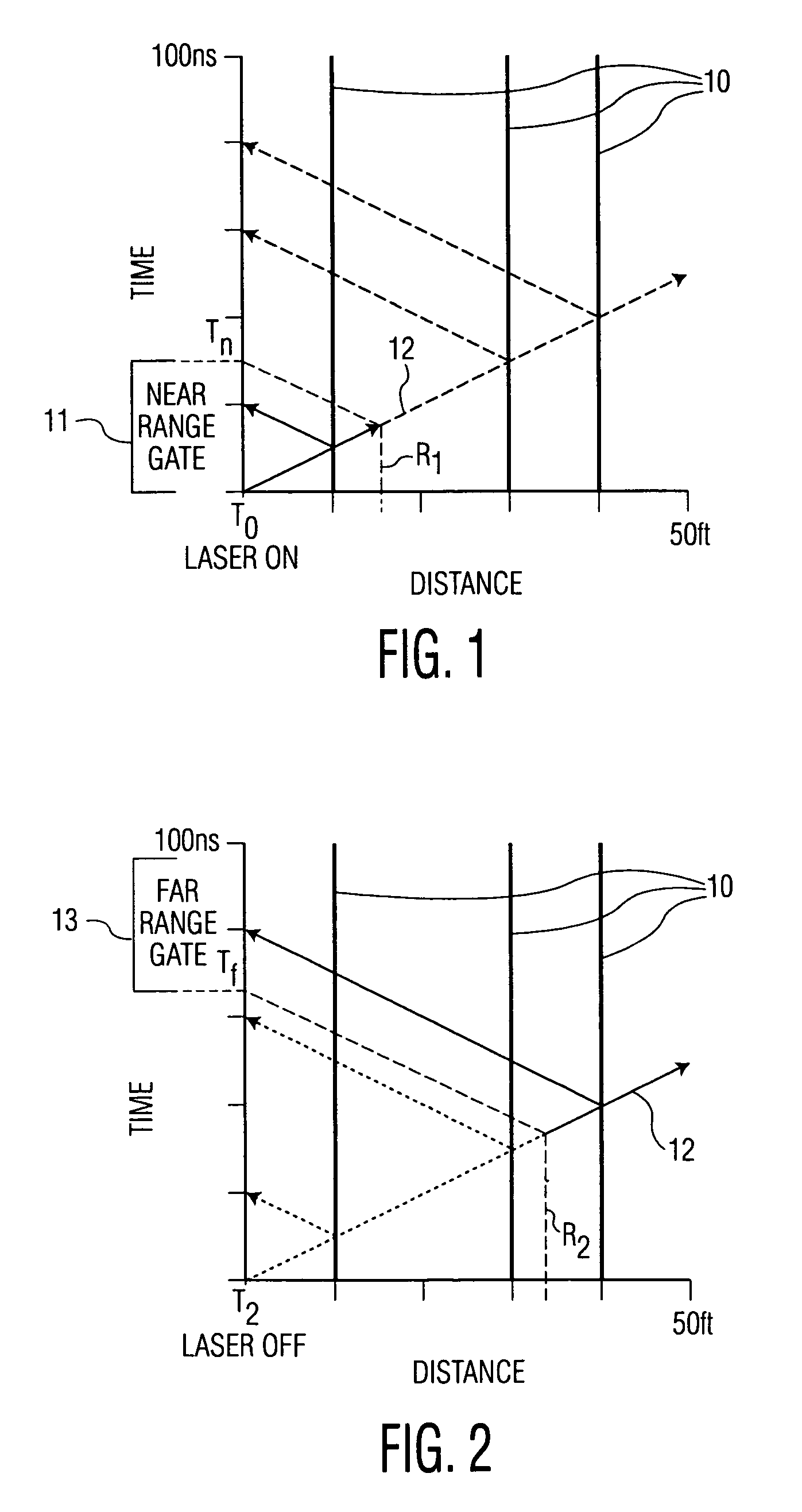
[0030]The invention provides two special cases where range resolution is not a function of the illuminator pulse width. These special cases are at minimum range (0 to Rmin) and at maximum range (Rmax to R∞). These two ranges are referred to herein as R1 and R2, respectively, and described below.

[0031]When imaging at the minimum range, camera gating (or an intensifier in the case of I2C systems) may be used to limit R1. FIG. 1 illustrates near range gating. The bars marked ‘reflectors’, generally designated as 10, are objects in the field of ...


PUM


Abstract

A collision avoidance system for a vehicle includes a collision avoidance processor, and an active sensor for obtaining successive range measurements to objects along a path transversed by the vehicle. The active sensor includes a near range gate for obtaining a near range measurement to objects located at a range less than a first predetermined range, and a far range gate for obtaining a far range measurement to objects located at a range greater than a second predetermined range. The near and far range measurements are provided to the collision avoidance processor for maneuvering of the vehicle.

Description

FIELD OF THE INVENTION[0001]The present invention relates, in general, to collision avoidance and, more specifically, to collision avoidance using a range gated camera.BACKGROUND OF THE INVENTION[0002]A vehicle often requires knowledge of its environment. This may be accomplished by integrating information derived from multiple onboard navigation sensors, such as a GPS (Global Positioning System) receiver, an IMU (Inertial Measurement Unit), an altimeter, etc. Using such sensors, the vehicle may obtain its own position, velocity and acceleration information. Information of obstacles in the path of the vehicle may also be obtained using onboard target tracking sensors to derive position and bearing information of targets proximate to the vehicle.[0003]By optimally integrating navigation sensors and target tracking sensors, guidance laws may be used to generate a desired trajectory for the vehicle.[0004]Generally, target tracking sensors produce range measurements of a target with res...

Claims


Application Information

Patent Timeline
IPC IPC(8): B60T7/16B60T7/22G01S13/18G01S13/88G01S13/89G01S13/931G08G1/16
CPCB60T7/22G01S13/18G01S13/89G01S13/931G05D1/0202G01S13/881G01S2013/9342G01S2013/9346G01S2013/9353G01S2013/9364G01S2013/9367G01S2013/936G01S2013/9318G01S2013/93185G01S2013/9323G01S2013/932G01S2013/9324G01S2013/9316
Inventor TRUDEAU, TIM K.
Owner ELBIT SYSTEMS OF AMERICA LLC
Why Eureka
Try Eureka