
Power system having a phase locked loop with a notch filter

a technology of phase lock and notch filter, which is applied in the direction of power conversion systems, instruments, electrical apparatus, etc., can solve the problems of uniegular voltages of line-to-line, harmonic disturbances on the line, and injection current demand that exceeds the system capacity, and achieves high frequency, amplitude and phase estimation. the effect of high accuracy

Inactive Publication Date: 2005-12-20
AMERICAN SUPERCONDUCTOR
View PDF7 Cites 38 Cited by
  • Summary
  • Abstract
  • Description
  • Claims
  • Application Information

AI Technical Summary

Benefits of technology

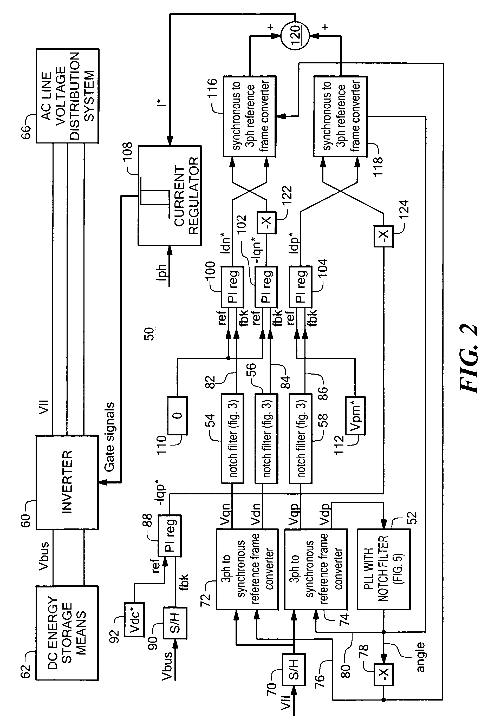
[0013]With this arrangement, harmonic components at the frequency of the control signal are effectively removed from the filtered signal, thereby enabling the PLL to provide a highly accurate frequency, amplitude and phase estimate of the selected sequence component. In one illustrative embodiment, the control signal has a level indicative of two times the frequency of the sampled line voltage so that the filter removes the second harmonic component from the selected sequence component, which harmonic component is attributable to the sequence component of opposite polarity. Accordingly, the filter removes the effect of the opposite polarity sequence component on the resulting angle signal.

Problems solved by technology

For example, a line-to-ground fault on one phase can cause the line-to-line voltages to become unequal.
Another power line quality problem is the presence of harmonic disturbances on the line, as can be caused by non-linear loads.
However, such a phase-by-phase analysis of the line voltage may result in an injected current demand that exceeds the system capacity or is ineffective in restoring voltage balance, since this type of analysis ignores interaction between the phases.
However, a tradeoff exists between the speed of response and elimination of the second harmonic components, since low pass filters result in significant response delays.
Non-linear loads contribute to the generation of undesirable harmonics on the DC bus.

Method used


Image

  • Power system having a phase locked loop with a notch filter
  • Power system having a phase locked loop with a notch filter
  • Power system having a phase locked loop with a notch filter

Examples


Embodiment Construction

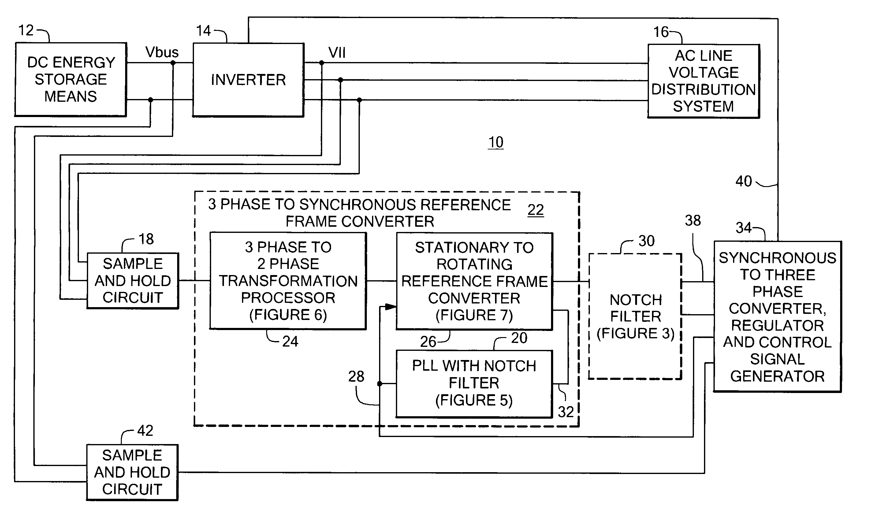
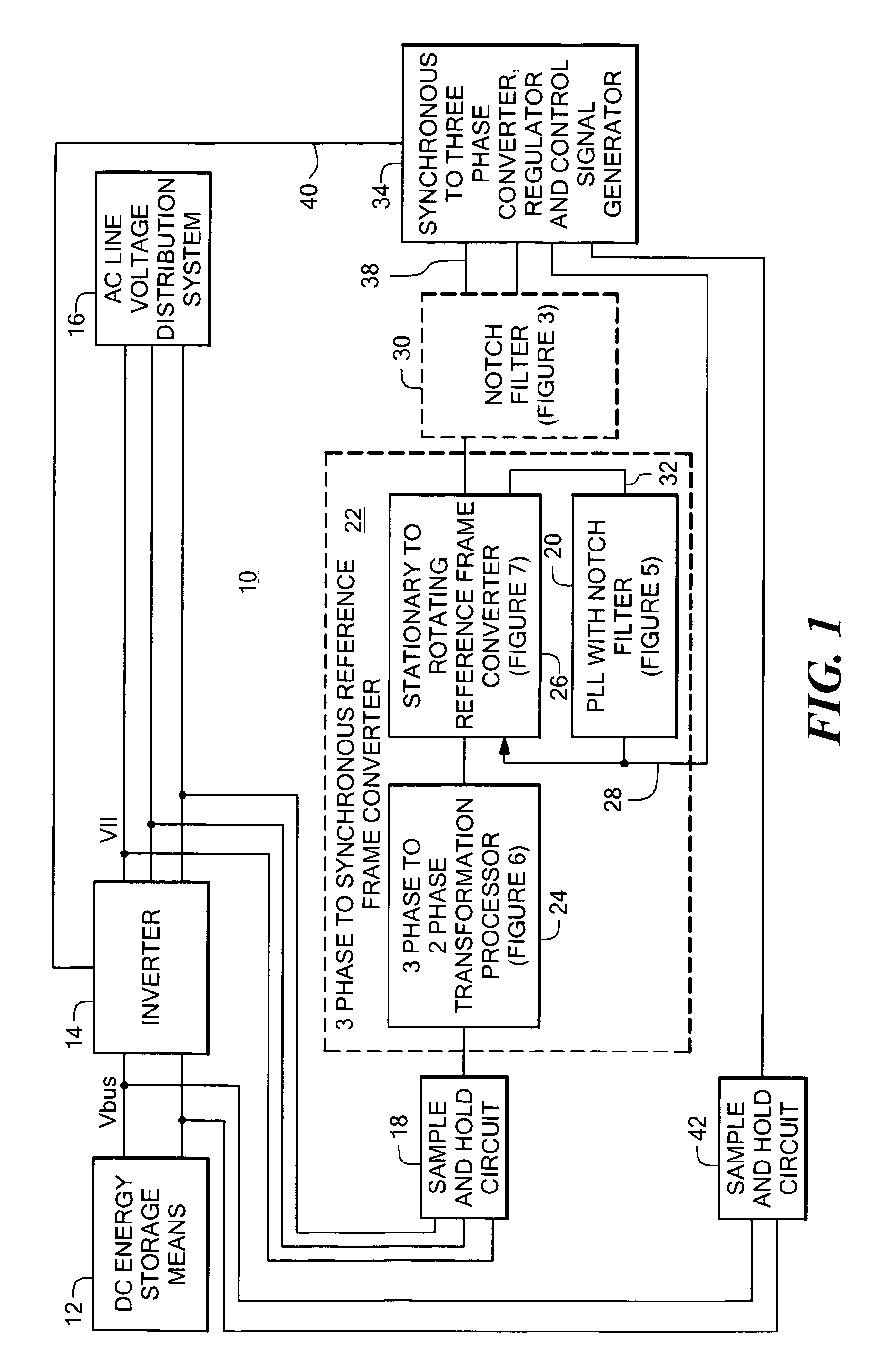
[0031]Referring to FIG. 1, a power system 10 includes an inverter 14 coupled in series between a DC energy storage means 12, such as a battery, DC bus capacitors or other energy storage means, and the AC line voltage distribution system 16. A sample and hold circuit 18 samples the line voltage V11 and the digitized line voltage is coupled to a three phase to a synchronous reference frame converter 22. The converter 22 includes a three phase to two phase transformation processor or simply, transformer 24 (FIG. 6) for transforming the sampled three phase quantities into two phase, x and y axis quantities. The output of the transformation processor 24 is coupled to the stationary to rotating reference frame converter 26 (FIG. 7) as shown which converts from the stationary x, y coordinates to a D, Q coordinate system locked to the phase of positive sequence. To this end, a phase locked loop (PLL) 20 is responsive to the D axis positive sequence component 32 for generating a synchronous ...


PUM


Abstract

A power system having a phase locked loop (PLL) with a notch filter for synchronous reference frame sequence separation. The notch filter includes a generalized integrator tuned to the notch frequency. The output of the generalized integrator is summed with the filter input signal and the output of the summer is fed back to the integrator input. In one embodiment, the notch filter is programmable by a control signal generated in response to the filter output signal, thereby causing the filter to self-regulate to a frequency related to the PLL input signal. Illustrative power systems include active VAR generators and active rectifiers. One or more additional notch filters may be used to remove harmonic components from derived synchronous reference frame sequence components.

Description

CROSS-REFERENCE TO RELATED APPLICATIONS[0001]Not Applicable.STATEMENT REGARDING FEDERALLY SPONSORED RESEARCH[0002]Not Applicable.FIELD OF THE INVENTION[0003]This invention relates to three phase power systems utilizing phase sequence separation and, more particularly, to a power system having a phase locked loop with a notch filter for use in phase sequence separation.BACKGROUND OF THE INVENTION[0004]Power line conditioning systems for monitoring the quality of an AC line voltage and restoring an unsatisfactory line voltage to within a specified voltage range are known. There are various causes for a line voltage to be outside of its specified range. For example, a line-to-ground fault on one phase can cause the line-to-line voltages to become unequal.[0005]Another power line quality problem is the presence of harmonic disturbances on the line, as can be caused by non-linear loads. Such harmonic disturbances take the form of AC currents on the power line at frequencies other than th...

Claims


Application Information

Patent Timeline
Patent Type & Authority Patents(United States)
IPC IPC(8): H02M1/12H02M7/5387
CPCH02M1/12H02M7/53871
Inventor GRITTER, DAVID J.
Owner AMERICAN SUPERCONDUCTOR
Learn More