Contact structures for sliding switches

a technology of contact structure and sliding switch, which is applied in the direction of contact, contact engagement, electrical apparatus, etc., can solve the problems of arc erosion, unstable voltage, and increased voltage, so as to prolong the service life of the switch and maintain voltage stability

Inactive Publication Date: 2005-12-27
DELPHI TECH INC
View PDF9 Cites 201 Cited by
  • Summary
  • Abstract
  • Description
  • Claims
  • Application Information

AI Technical Summary

Benefits of technology

[0013]The present invention provides contact structures for a sliding switch capable of extending the service life of the switch while maintaining voltage stability as compared with a conventional contact structure.
[0014]In accordance with a first aspect of the present invention, an improved contact structure is provided for a sliding switch having a stationary contact pad and a movable contact that is capable of directing accumulation of arcing debris away from a portion of a steady state contacting zone on the stationary contact pad. Consequently, a portion of the contacting area between stationary and movable contacts remains generally free of arcing erosion debris for an extended portion of the service life of the switch, thus extending the service life and improving voltage stability as compared to a conventional configuration.
[0017]In accordance with a second aspect of the present invention, a contact configuration is provided which is capable of directing arcing toward the contact pad connected to the positive terminal of a power source and away from contact pads connected to a negative terminal. This configuration is advantageous because accumulation of conductive arcing debris between adjacent stationary contact pads is reduced compared with configurations known in the art. Thus, dielectric strength between adjacent contact pads is maintained over an extended portion of the service life of a switch.
[0019]In accordance with a third aspect of the present invention, a contact configuration is provided which is capable of directing arcing to occur simultaneously at a contact pad connected to a negative terminal and a contact pad connected to a positive terminal. Consequently, arcing energy is split between each contact pad. This configuration results in a decreased formation of arcing erosion debris at the contact pad connected to the negative terminal as compared to the amount generated by configurations known in the prior art.

Problems solved by technology

The current flowing through the gap between contacts generates heat, resulting in temperatures high enough to cause arc erosion; some of the nearby insulation may be burned away.
In the illustrated example, voltage begins to increase and become unstable after about 25 arcing cycles.
Debris on the insulation material reduces the dielectric strength of the insulation.

Method used


Image

  • Contact structures for sliding switches
  • Contact structures for sliding switches
  • Contact structures for sliding switches

Examples


Embodiment Construction

[0039]As discussed above, contact configurations in accordance with the present invention are capable of providing an increased number of switching cycles while providing a more stable resistance across contacts than achieved by known contact configurations.

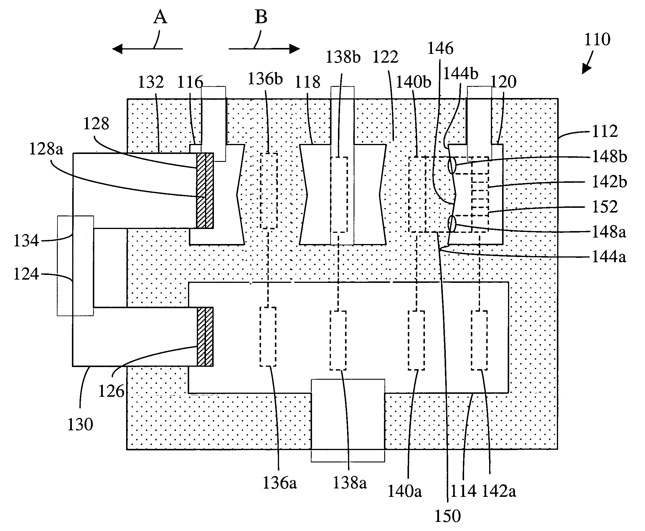
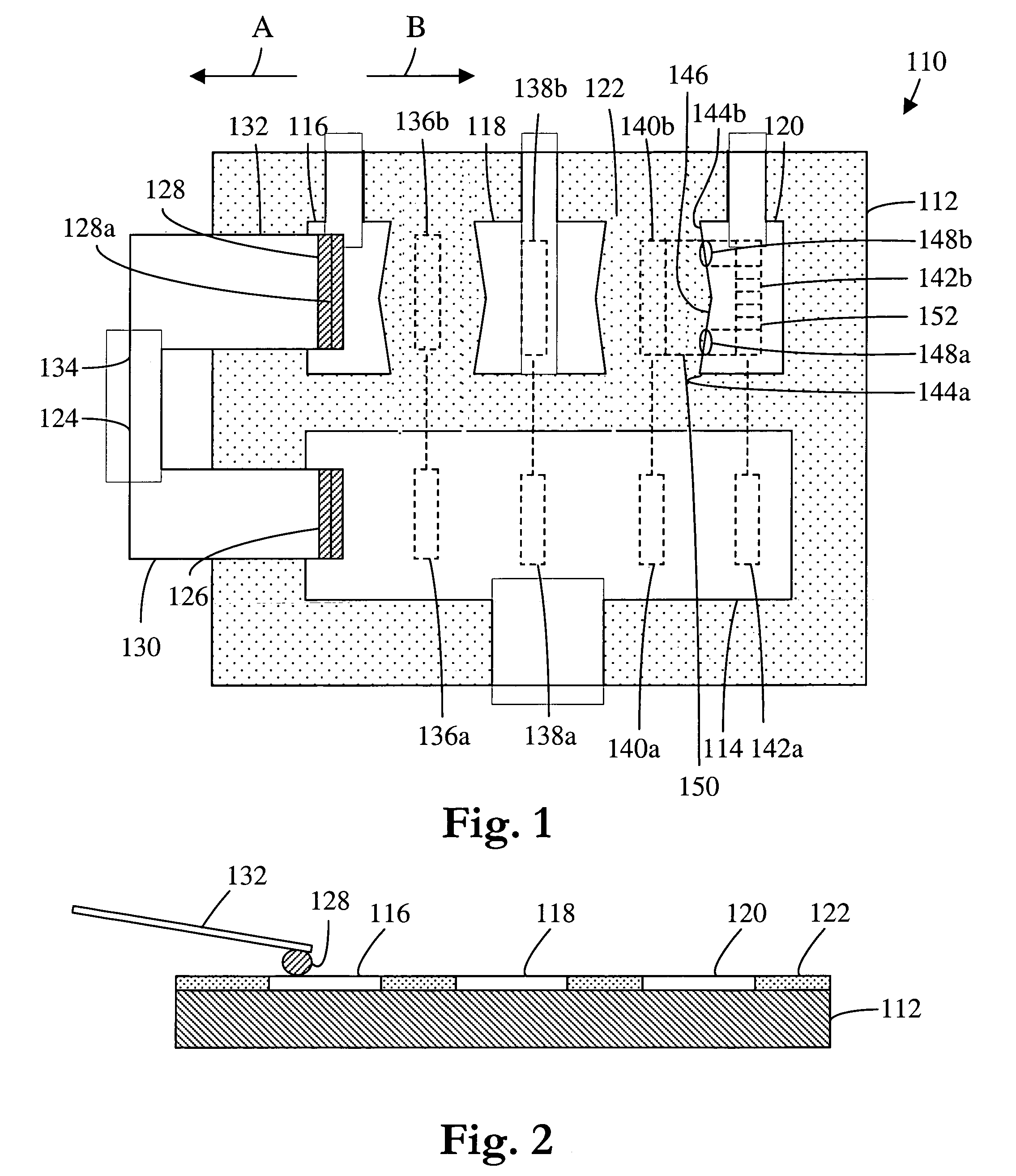
[0040]Referring to the figures, FIGS. 1–2 illustrate a first exemplary embodiment of a contact configuration 110 for a sliding switch.

[0041]A circuit board substrate 112 is formed of a synthetic resin made of an insulating material. A first conductive stationary contact pad 114 connected to a positive terminal of a power source is disposed on substrate 112. Second, third, and fourth conductive stationary contact pads 116, 118, 120 connected to a negative terminal of a power source via a ground connection are disposed on substrate 112. An insulating material 122 such as a solder mask is disposed between contact pads 114, 116, 118, 120.

[0042]A conductive movable contact assembly 124 is mounted to an unillustrated holder which permi...


PUM


Abstract

A contact structure for a sliding switch includes a conductive stationary contact disposed on a base and a conductive movable contact for electrically contacting the stationary contact. The movable contact is movable along a path between a non-contact position and a make-contact position with respect to the stationary contact, and at least one of the contacts has a protruding portion that provides an electrical interface for discharge of arcing as the movable contact breaks from the stationary contact. As a result, the invention prevents or substantially reduces degradation in switch performance which might otherwise be caused by debris accumulation associated with arcing.

Description

TECHNICAL FIELD[0001]The present invention relates generally to the structure of contacts of a sliding switch and, in particular, to the structure and configuration of stationary and movable contacts.BACKGROUND OF THE INVENTION[0002]There is a growing demand for sliding switches that use printed circuit boards, wire frames, and the like as stationary contacts. Such switches are used in vehicles (e.g., to control lights, turn signals, etc.), in household devices (e.g., as program switches for washers and dryers, etc.), and many other applications.[0003]A conventional arrangement and structure of contacts of a sliding step switch is shown in FIGS. 12–14. The arrangement depicts a three function configuration 510 for a sliding switch. A circuit board substrate 512 is formed of a synthetic resin made of an insulating material. A first conductive stationary contact pad 514 connected to a positive terminal of a power source is disposed on substrate 512. Second, third, and fourth conductiv...

Claims


Application Information

Patent Timeline
Patent Type & Authority Patents(United States)
IPC IPC(8): H01H1/40H01H3/48H01H9/38H01H15/00H01H15/04H01H19/00
CPCH01H9/38H01H1/403H01H15/04
Inventor AUKLAND, NEIL RSCHOEPF, THOMAS JDREW, GEORGE ALBERTRUDOLPH, GERD
Owner DELPHI TECH INC
Why Eureka
Try Eureka