Method and system for providing tunable dispersion compensation

a technology of tunable dispersion and compensation, applied in the field of providing tunable dispersion compensation, can solve the problems of dcf not providing full compensation, dcf length must be altered,

Inactive Publication Date: 2005-12-27
CIENA
View PDF19 Cites 13 Cited by
  • Summary
  • Abstract
  • Description
  • Claims
  • Application Information

AI Technical Summary

Problems solved by technology

A drawback to the DCF compensation schemes described above is that DCF lengths must be altered to if the length of transmission fiber is changed in order to provide the same amount of compensa...

Method used


Image

  • Method and system for providing tunable dispersion compensation
  • Method and system for providing tunable dispersion compensation
  • Method and system for providing tunable dispersion compensation

Examples


Embodiment Construction

[0023]The following detailed description of the invention refers to the accompanying drawings. The same reference numbers in different drawings identify the same or similar elements. Also, the following detailed description does not limit the invention. Instead, the scope of the invention is defined by the appended claims and equivalents thereof.

[0024]The expression “optically communicates” as used herein refers to any connection, coupling, link or the like by which optical signals carried by one optical system element are imparted to the “communicating” element. Such “optically communicating” devices are not necessarily directly connected to one another and may be separated by intermediate optical components or devices. Likewise, the expressions “connection” and “operative connection” as used herein are relative terms and do not require a direct physical connection.

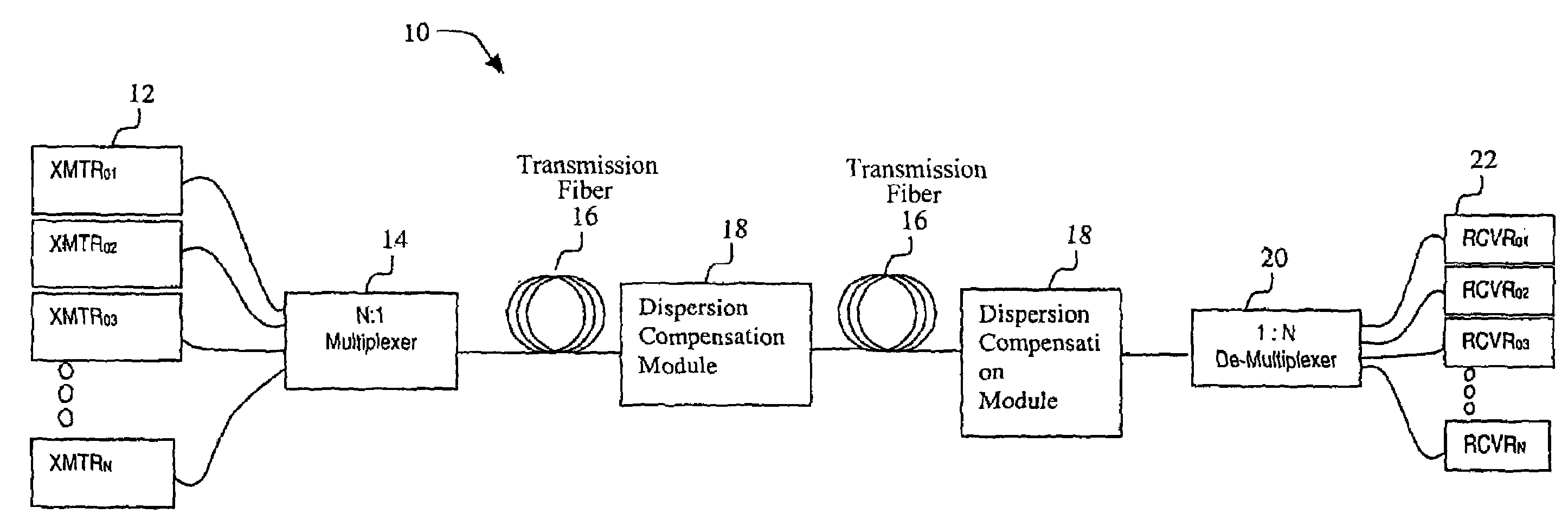
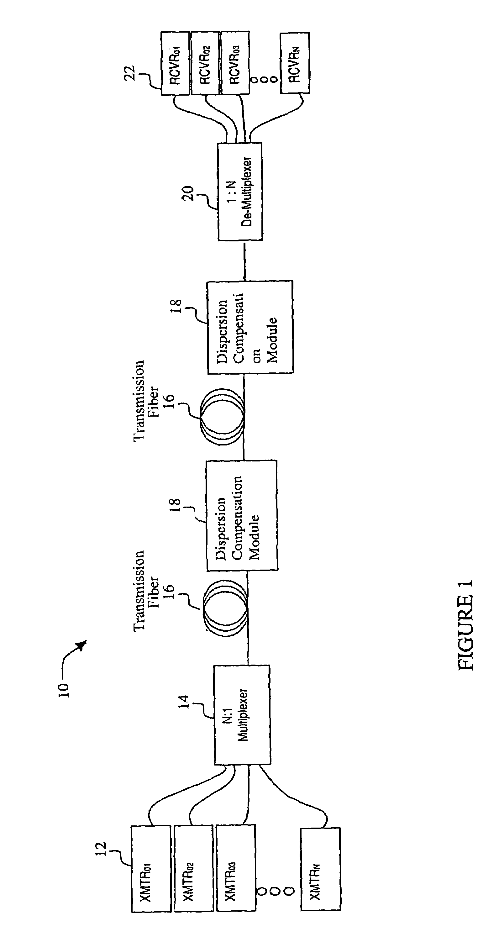
[0025]FIG. 1 depicts an optical communications network 10 in an exemplary embodiment of the invention. The network 10 ...


PUM


Abstract

An exemplary embodiment of the invention is a dispersion compensation module for compensating dispersion in a communications network. The dispersion compensation module includes dispersion compensating fiber having a dispersion coefficient that varies with wavelength. A thermal regulator adjusts the temperature of the dispersion compensating fiber to adjust the dispersion characteristic of the dispersion compensating fiber. Alternate embodiments of the invention include a communications system using the dispersion compensation module and a method for compensating dispersion.

Description

CROSS REFERENCE TO RELATED APPLICATION[0001]The present application claims the benefit under 35 U.S.C. § 119(e) of the filing date of U.S. Provisional Application Ser. No. 60 / 264,335, filed Jan. 26, 2001, the teachings of which are incorporated herein by reference.BACKGROUND OF THE INVENTION[0002]1. Field of Invention[0003]The invention relates generally to a method and system for providing tunable dispersion compensation.[0004]2. Description of Related Art[0005]Dispersion is a known phenomenon in optical networks that causes a broadening of optical pulses along the length of the fiber. One type of dispersion relevant to the present invention is chromatic dispersion (also referred to as “material dispersion” or “intramodal dispersion”), caused by a differential delay of various wavelengths of light in a waveguide material.[0006]The spectrum associated with a transmitted optical signal is subject to modulation-induced broadening, which increases linearly with bit rate. At the same ti...

Claims


Application Information

Patent Timeline
IPC IPC(8): H04B10/08H04B10/18
CPCH04B10/2525
Inventor FRANKEL, MICHAEL Y.MIZRAHI, VICTOR
Owner CIENA
Why Eureka
Try Eureka