
Wire cutter and bayonet sheath combination

Active Publication Date: 2006-01-03
ACME UNITED CORPORATION
View PDF5 Cites 5 Cited by
  • Summary
  • Abstract
  • Description
  • Claims
  • Application Information

AI Technical Summary

Benefits of technology

[0008]It is therefore a principal object and advantage of the present invention to provide a cutting tool that may be used in conjunction with or apart from a scabbard.

Problems solved by technology

While very functional and useful, tools constructed in this manner are relatively time consuming and difficult to assemble.
Although this type of tool is quicker and easier to set up and use than the typical tool previously described, because it must be used in combination with the scabbard which also serves to hold the knife, its usefulness is some what limited and it is some what cumbersome to maneuver and use.

Method used


Image

  • Wire cutter and bayonet sheath combination
  • Wire cutter and bayonet sheath combination
  • Wire cutter and bayonet sheath combination

Examples


Embodiment Construction

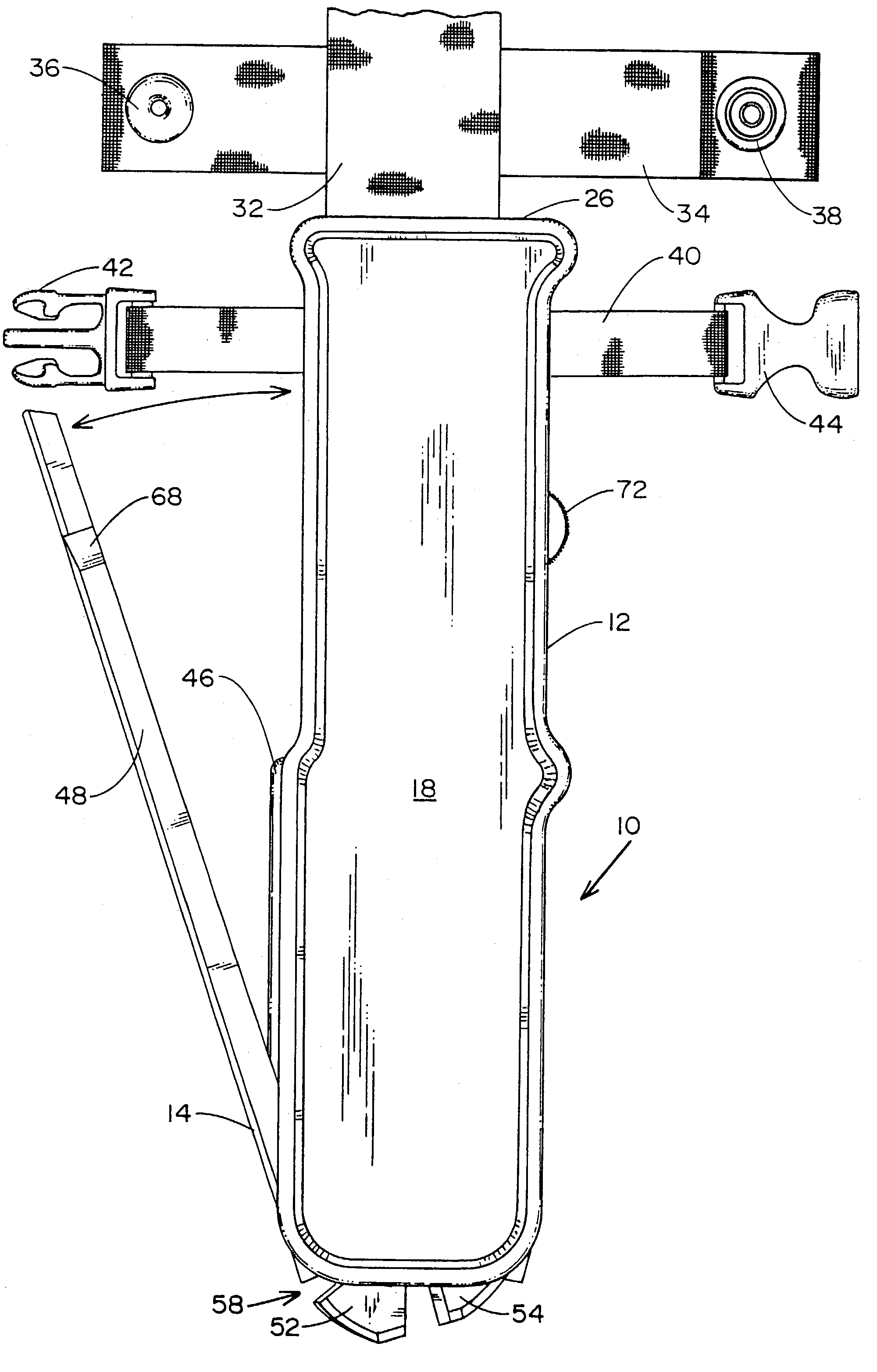
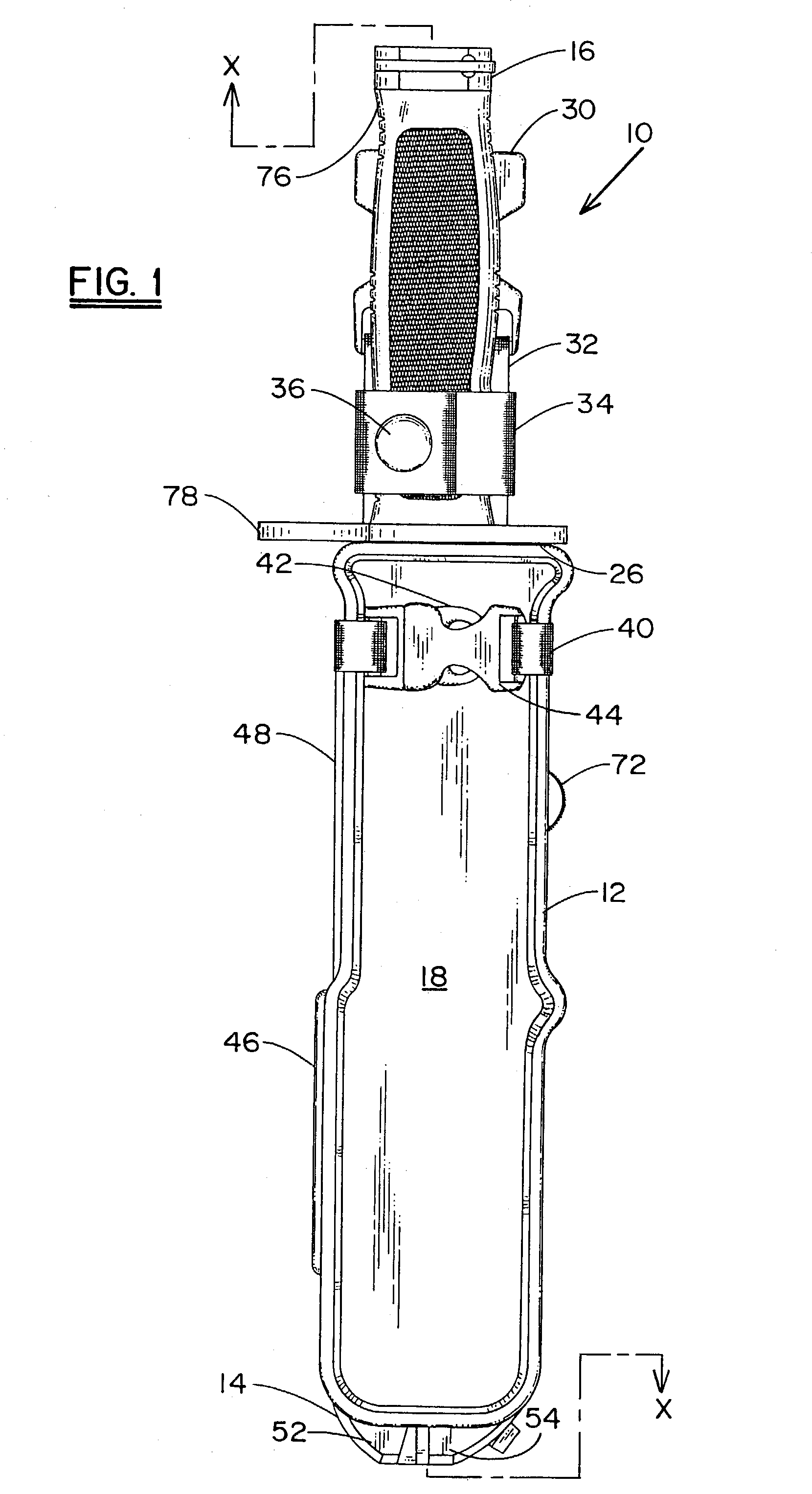
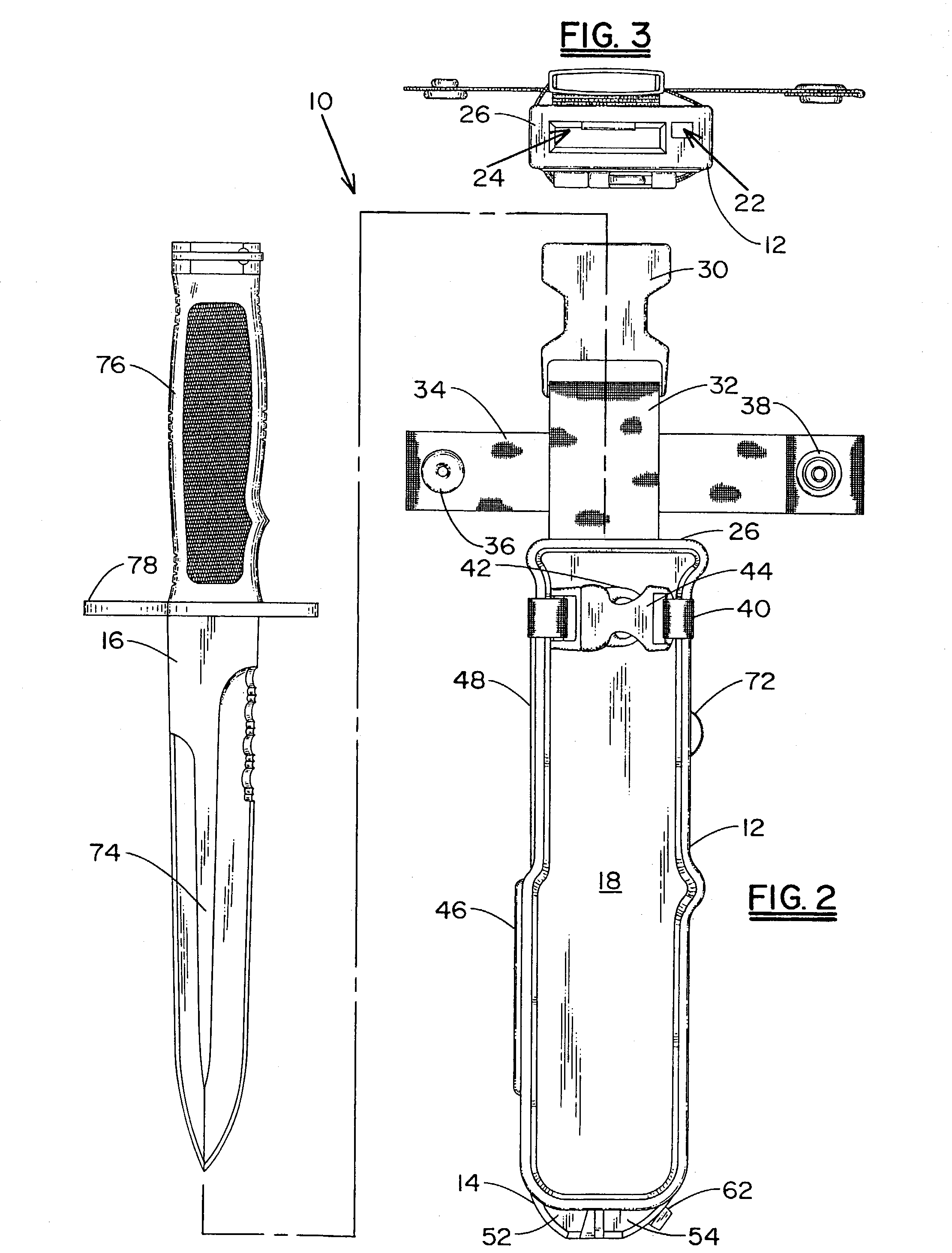
[0025]Referring now to the drawings, wherein like reference numerals refer to like parts throughout, there is seen in FIG. 1 a combination tool, designated generally by reference numeral 10, generally comprising a scabbard 12, a cutting tool 14, and a combat knife 16. As will be explained in greater detail hereinafter, scabbard 12 is adapted to be worn on the belt of a person and carry cutting tool 14 and combat knife 16 therein.

[0026]Scabbard 12 generally comprises a body having front and rear major surfaces 18, 20, and extends along a longitudinal axis X—X. An elongated channel 22 is formed through scabbard 12, extending in spaced, parallel relation to longitudinal axis X—X, and a cavity 24 is formed in the top end 26 of scabbard 12 and extends along axis X—X. A belt loop fixture 28 is attached to rear surface 20 to permit scabbard 12 to be attached to a person via a belt, and a conventional female connector 30 fixed to the end of a flexible strap 32 is also attached to rear surfa...


PUM


Abstract

The present invention provides a scabbard for a combat knife and cutting tool combination. The scabbard generally comprises a body extending along a longitudinal axis between first and second ends, and includes a channel formed therethrough that extends in spaced, parallel to the longitudinal axis, and a cavity that extends along the longitudinal axis. The cutting tool comprises first and second legs pivotally interconnected to one another that extend along longitudinal first and second axes, respectively, with the first leg being removably positionable within the channel of the scabbard, and the second leg being movable relative to the scabbard, but held firmly in position by a releasable strap when the tool is not in use. A combat knife is removably positionable in the cavity of the scabbard.

Description

BACKGROUND OF THE INVENTION[0001]1. Field of Invention[0002]The present invention relates generally to combat knife scabbards, and more particularly to scabbards having a wire cutting tool provided therewith.[0003]2. Description of Prior Art[0004]Combat knives and bayonets are sometimes held in scabbards that may be worn on a person. Often, a wire cutting tool is separately incorporated with the knife and scabbard, or provided as an integral feature of the knife and scabbard. The purpose of the cutting tool is generally to cut through wire, such as chain link fencing, or to snip metal, thereby adding functionality to the knife and scabbard combination.[0005]In their most traditional form, the scabbard and cutting tool combinations comprise a bolt or boss protruding outwardly from one surface of the scabbard. The knife includes one edge that is beveled in a manner making it conducive to cutting wire, and includes an opening formed through the body of the blade that is adapted to secu...

Claims


Application Information

Patent Timeline
IPC IPC(8): B26B11/00B26B17/00B26B29/02
CPCB26B29/025B26B17/00
Inventor TERZUOLA, ROBERT
Owner ACME UNITED CORPORATION
Learn More