
Orthopedic casting slipper kit and method

a technology of orthopaedic casting and foot impressions, which is applied in the field of orthopaedic casting slipper kits and methods, can solve the problems of time-consuming, messy, and unfavorable custom casting, and achieve the effect of reducing the accuracy of custom casting

Inactive Publication Date: 2006-01-03
GRAF PETER M +1
View PDF18 Cites 2 Cited by
  • Summary
  • Abstract
  • Description
  • Claims
  • Application Information

AI Technical Summary

Benefits of technology

The kit provides a more accurate, efficient, and mess-free method for creating custom foot impressions, ensuring better arch support and allowing for the production of multiple orthotics without the need for scissors or cast cutters.

Problems solved by technology

This procedure was time-consuming, messy, somewhat inaccurate and the custom casting impression which was made was suitable only for making a single positive mold of the foot.
While the approach taken in Friedman reduced some of the messiness and handling problems, there were still substantial disadvantages.
The Friedman pre-shaped slipper form only loosely fit the patient's foot, and when moistened with water, the operator had to press or fold the plaster of paris containing cloth down against the foot, which was messy and created folds which detracted from the accuracy of the custom casting.
Friedman also had the disadvantage of being capable of making only a single positive foot replica from the custom impression.
Casting the arch using the BIO-FOAM system can cause problems in that pushing down on the foam to deform it tends to flatten the arch.
Shipping the deformed foam cast from the technician taking the impression to the laboratory making the positive cast also can result in damage to the deformed foam impression.
It has been found, however, that the use of such casting sleeves for the formation of orthotics that engage primarily the plantar surface of the foot is not very practical.
The prior art impression sleeve comes up undesirably high on the patient's foot, and there is a tendency for the elasticity of the fabric to cause the sleeve to “bridge” or “tent” in the area of the arch of the foot.
Since orthotics often are designed to provide arch support, such bridging or tenting is highly undesirable.

Method used


Image

  • Orthopedic casting slipper kit and method
  • Orthopedic casting slipper kit and method
  • Orthopedic casting slipper kit and method

Examples


Embodiment Construction

[0020]Reference will now be made in detail to the preferred embodiment of the present invention, an example of which is illustrated in the accompany drawing. While the invention will be described in conjunction with the preferred embodiment, it will be understood that it is not intended to limit the invention to that embodiment. On the contrary, the invention is intended to cover alternatives, modifications and equivalents which may be included within the spirit and scope of the invention as defined by the appended claims.

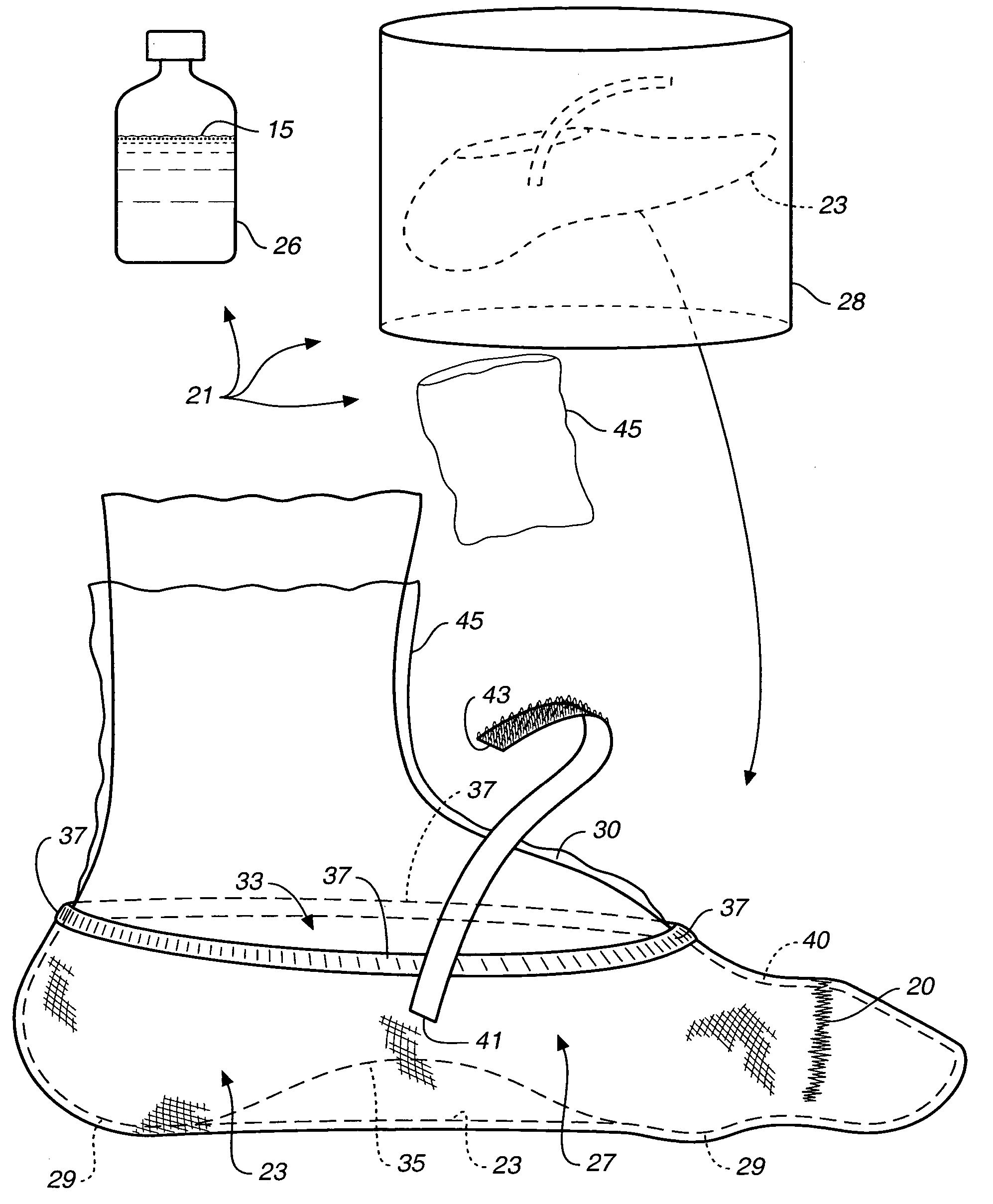
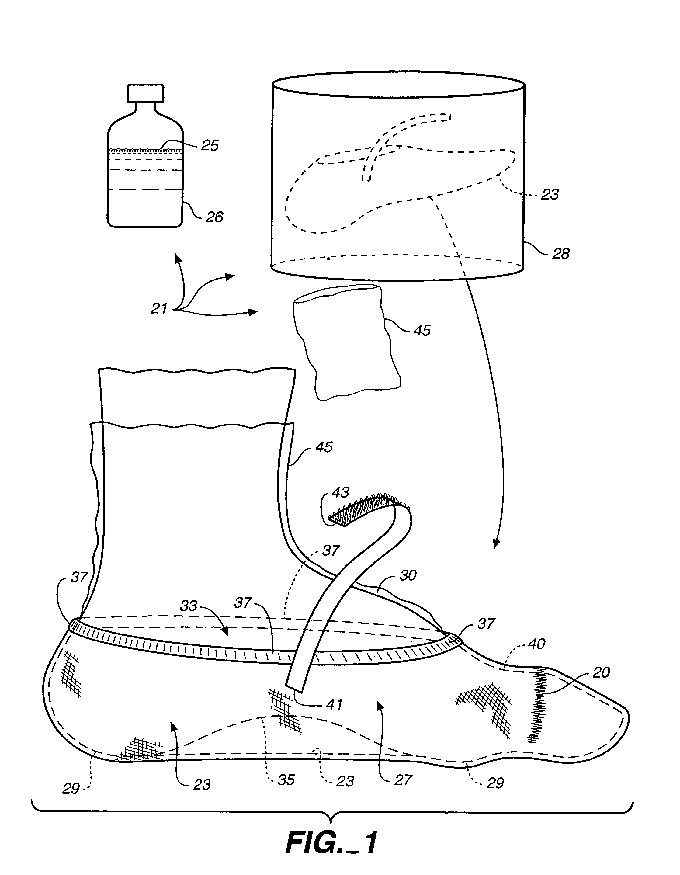
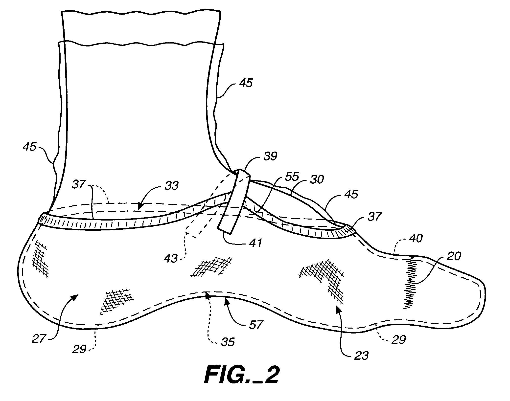
[0021]The orthopedic casting slipper kit, generally designated 21, of the present invention includes a resilient fabric impression slipper 23 and a quantity of curable resin 25 sufficient to harden fabric slipper 23 into an impression of a patient's foot 27 and particularly the plantar surface 29 thereof. Impression slipper 23 has the shape of a relatively low-cut slipper and it extends from plantar aspect or surface 29 of the patient's foot up to a position below ...


PUM

PropertyMeasurementUnit
thicknessaaaaaaaaaa
areaaaaaaaaaaa
distanceaaaaaaaaaa

Abstract

An orthopedic casting slipper kit (21) including a resilient fabric impression slipper (23) formed to extend on a patient's foot (27) from a plantar aspect or surface (29) to about one-third of the way from the base of the toes to the dorsum of the foot. A longitudinally resiliently extensible band (37) is provided on the slipper (23) proximate the open end (33), and an arch strap (39) dimensioned to span transversely over the dorsum (30) of the foot (27) is used to pull the impression slipper (23) up into contact with the arch (35) of the foot to prevent bridging of the arch. A method of using the arch strap (39) to aid in conformance also is disclosed.

Description

TECHNICAL FIELD[0001]The present invention relates, in general, to kits and methods for making custom molded impressions useful for the formation of orthopedic devices, and more particularly, relates to kits and methods for making custom molded foot impressions for the formation of orthotics.BACKGROUND ART[0002]Considerable effort has been directed toward the custom molding or formation of foot impressions or casts which, in turn, may be used to form foot orthotic devices. Early approaches included the use of gauze strips and plaster of paris to build up a casting or custom impression of the foot which, when hardened, was removed from the foot. A positive impression was made inside the hardened casting, and then the negative cast was removed and the orthotic device made from the positive impression.[0003]This procedure was time-consuming, messy, somewhat inaccurate and the custom casting impression which was made was suitable only for making a single positive mold of the foot.[0004]...

Claims


Application Information

Patent Timeline
Patent Type & Authority Patents(United States)
IPC IPC(8): B29D31/50A43B7/28B29D35/00A43D1/02B29C33/38B29D35/02B29D35/04B29D35/14
CPCA43B7/141A43B7/28A43D1/022B29D35/14B29C33/3857B29D35/02B29D35/04A43D999/00
Inventor GRAF, PETER M.STESS, RICHARD M.
Owner GRAF PETER M
Learn More