Method and apparatus for orthopedic cast removal utilizing a rotary impact driver

a technology of rotary impact and orthopedic cast, which is applied in the field of method and apparatus for orthopedic cast removal utilizing rotary impact driver, can solve the problems of not being pleasant to patients, noisy saws, and often producing dust, so as to achieve less tendency to be bent and easy to expos

Inactive Publication Date: 2013-11-07
PERRIER GREGORY +1
View PDF6 Cites 2 Cited by
  • Summary
  • Abstract
  • Description
  • Claims
  • Application Information

AI Technical Summary

Benefits of technology

[0015]The wire is supplied mounted onto a release substrate which is peeled off a tape prior to using the same wire-attached tape to attach the wire to the patient prior to embedding it in the cast material. If the release substrate is semi-rigid, the mounted wire (which is not springy) will have less tendency to be bent before use. A free end of the wire is bent away from the patient and will rise beyond the finished cast by about 3″. It is then bent over and embedded near the outer surface of the cast so that it can be easily exposed prior to removal. The distal end of the wire is looped into a cast-engaging configuration free of tape so that it acts as an anchor to resist pulling through during the removal phase.

Problems solved by technology

The process itself is not pleasant for the patient.
Pediatric patients are often intimidated by the sawing.
The saws are noisy and usually produce much dust in the cutting operation.
This tends to be a slow operation which also transfers substantial reaction force and torque to the patient during the removal process.
Both of these requirements indicate that the specially designed removal device drive head as well as its battery supply may be bulky and expensive.

Method used


Image

  • Method and apparatus for orthopedic cast removal utilizing a rotary impact driver
  • Method and apparatus for orthopedic cast removal utilizing a rotary impact driver
  • Method and apparatus for orthopedic cast removal utilizing a rotary impact driver

Examples


Embodiment Construction

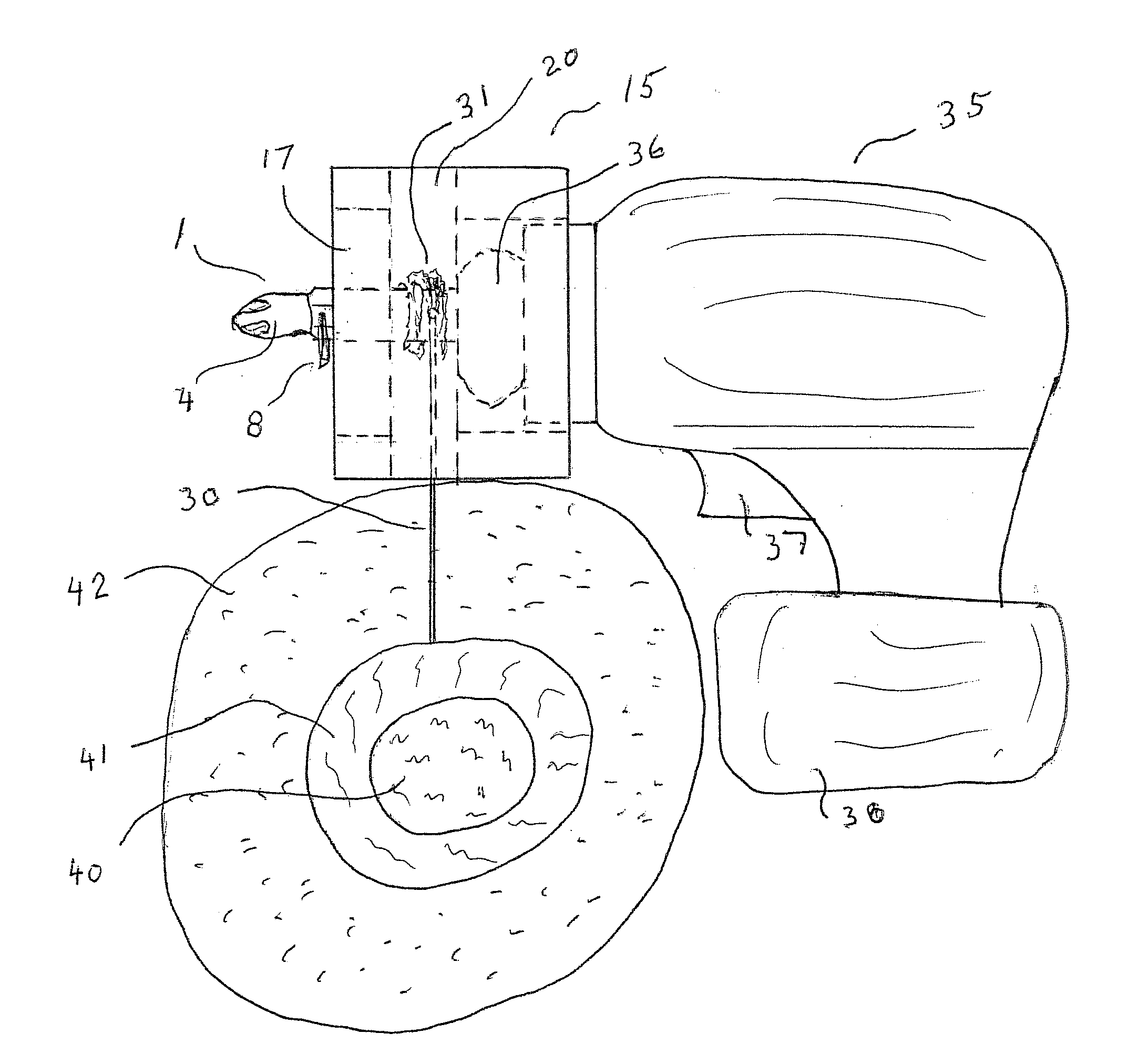
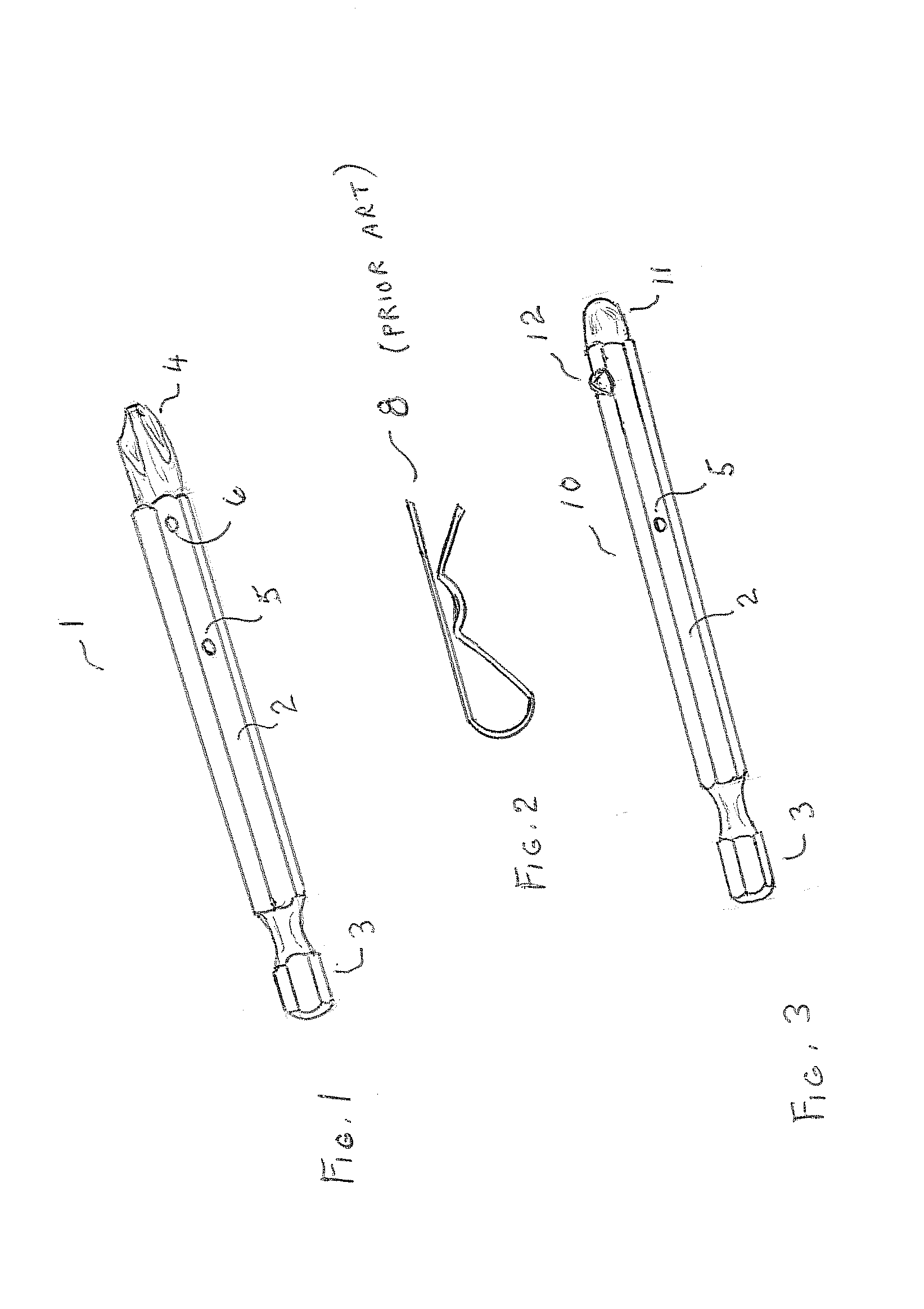
[0025]The apparatus of this invention comprises several parts. The wire winding mandrel 1 is shown at FIG. 1. In this case mandrel 1 is simply an ordinary Phillips screw driver bit compatible with a rotary impact driver with chucking end 3 hexagonal crossectional shaft 2 and driver end 4 with the addition of two transverse holes. Hole 5 is to engage the free end of the cutting wire and hole 6 is to accommodate locking clip 8 as shown in FIG. 2. An alternate embodiment of mandrel 10 is shown in FIG. 3. This also has the chuck engagement features 3, the hexagonal shaft 2 and wire end hole 5, but instead of a second hole an automatic self-locking spring-loaded ball 12 is used near the distal end which is now just a rounded contour 11. When using mandrel 10, no locking clip is used. It is simply snapped through the bearing hole in the slotted spacer block bearing.

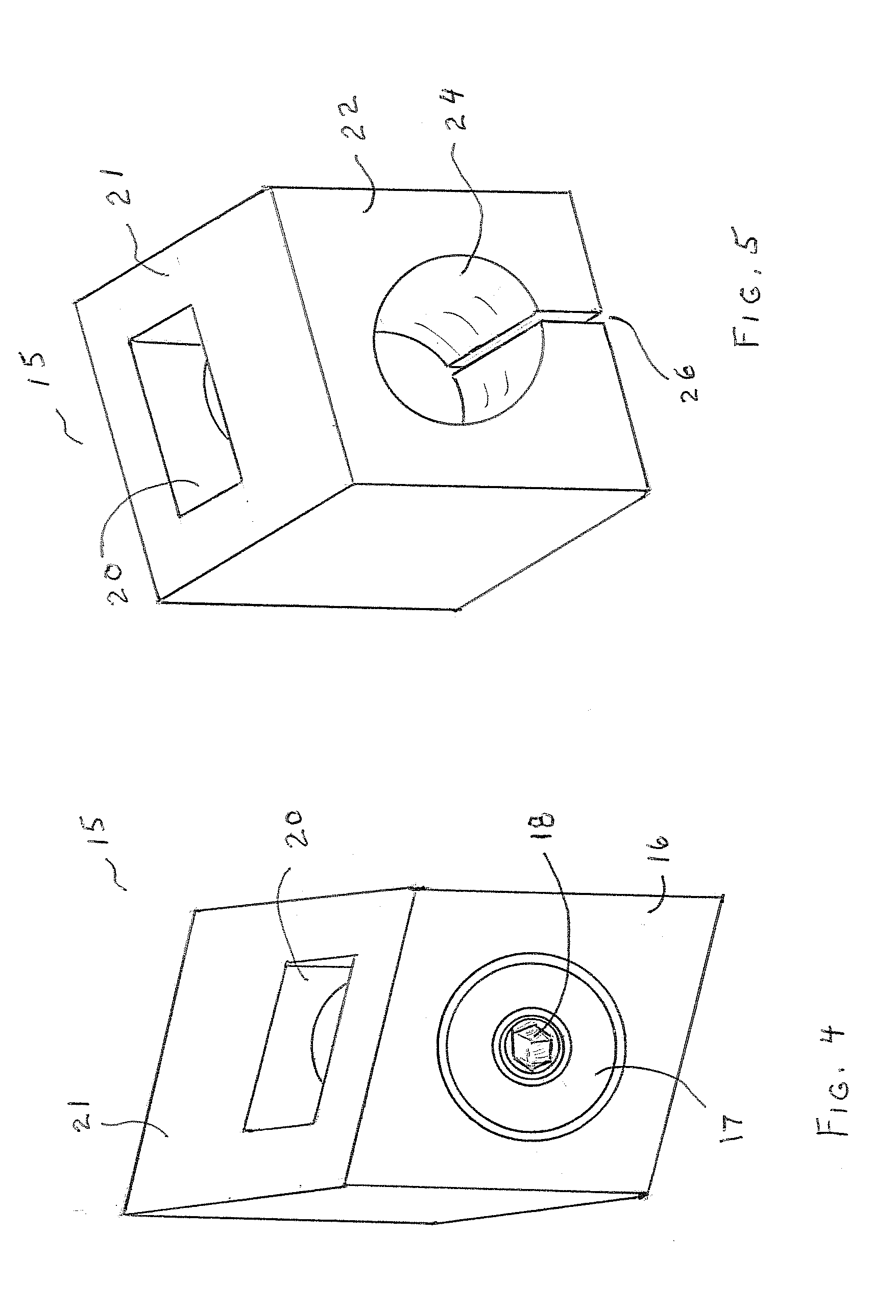
[0026]Slotted spacer block 15 is shown in FIGS. 4 and 5. The front face 16 of FIG. 4 is shown to have a mounted ball bearing ...


PUM

PropertyMeasurementUnit
thicknessaaaaaaaaaa
reaction forceaaaaaaaaaa
torqueaaaaaaaaaa

Abstract

An orthopedic cast removal tool and method uses an unmodified, typically cordless, rotary impact driver and a embedded wire to cut through an orthopedic cast for removal. By merging it with a slotted spacer block specifically for this cast removal purpose, an ergonomic tool is provided which allays fears of orthopedic patients. When rotating and encountering high resistance of the plaster or fiberglass material of the cast, the cordless rotary impact driver does not bog down; since it seamlessly engages impact action, which offers an order of magnitude or more torque multiplication via short frequent pulses (several per second) to overcome this torque resistance. Thus a high amount of torque with very little reaction force is made available to cut through a cast while affording the technician good control. The cast is cut very rapidly with little dust creation and no jostling of the patient.

Description

RELATED APPLICATIONS[0001]This application is based upon provisional patent application Ser. No. 61 / 639,679 filed on Apr. 27, 2012, and claims priority therefrom, pursuant to 28 U.S. Code §119(e). That application is incorporated by reference herein.BACKGROUND OF THE INVENTION[0002]Electrically driven saws are generally used for removing plaster or resin type orthopedic casts on human limbs or appendages. A cut is made and then the cast is split for removal. The process itself is not pleasant for the patient. Pediatric patients are often intimidated by the sawing. The saws are noisy and usually produce much dust in the cutting operation.[0003]The prior art shows an alternate method that involves the use of an embedded wire or strand which is attached to the surface of a patients limb prior to embedding in the cast itself. By pulling the wire through the cast, the cutting action will separate the cast for removal thereby avoiding the use of a saw with its noise and dust drawbacks.[00...

Claims


Application Information

Patent Timeline
Patent Type & Authority Applications(United States)
IPC IPC(8): A61F15/02
CPCA61F15/02
Inventor PERRIER, GREGORYMIZZI, JOHN
Owner PERRIER GREGORY
Why Eureka
Try Eureka