Rubber dam clamps retained by adhesion and improved frictional forces

a technology of rubber dam and frictional force, which is applied in the field of rubber dam clamps, can solve the problems of not always stable on the tooth, rubber dam failure during application, frustrating and time-consuming task of stopping the procedure, etc., and achieve the effect of improving frictional retention and frictional retention

Inactive Publication Date: 2006-01-03
HEASLEY JOHN M
View PDF6 Cites 34 Cited by
  • Summary
  • Abstract
  • Description
  • Claims
  • Application Information

AI Technical Summary

Problems solved by technology

One of the disadvantages and shortcomings of prior art rubber dam clamps is that they are not always stable on the tooth because they are simple mechanical devices that only approximate the contours of teeth, which vary widely in size and anatomical configuration.
Prior art rubber dam clamps very often shift in position during a dental procedure, pinching the patient's gums and completely dislodge, causing the rubber dam to fail during application.
When this happens, the frustrating and time-consuming task of stopping the procedure, re-applying the rubber dam clamp, and stretching the rubber dam over the clamp and an external frame must take place before resuming the operative procedure.
Prior art rubber dam clamps may also be vertically unstable and are prone to rotation and tipping about an axis due to the design of their clasping components.
In addition to the disadvantages of painful impingement on the patient's gums, the sharp metal clasps which contact the tooth either on enamel or cementum, the exposed dentine on the root surface, have been known to leave scratch marks or defects which later can be the focus for plaque accumulation and subsequent decay.
Not only does the disclosure fail to describe a device separate from a rubber dam, there is also no true reciprocal mechanism to apply reciprocal forces in a clamping action in order to grasp an object, the tooth in this instance, in order to hold itself in position.
This results in vector forces in a cervical direction which deflect the clasps of the clamp cervically against the gingival tissues, consequently causing impingement and pain to the patient.
Thus the tendency for the clamp to impinge on the gingival is still present in this device.

Method used


Image

  • Rubber dam clamps retained by adhesion and improved frictional forces
  • Rubber dam clamps retained by adhesion and improved frictional forces
  • Rubber dam clamps retained by adhesion and improved frictional forces

Examples


Embodiment Construction

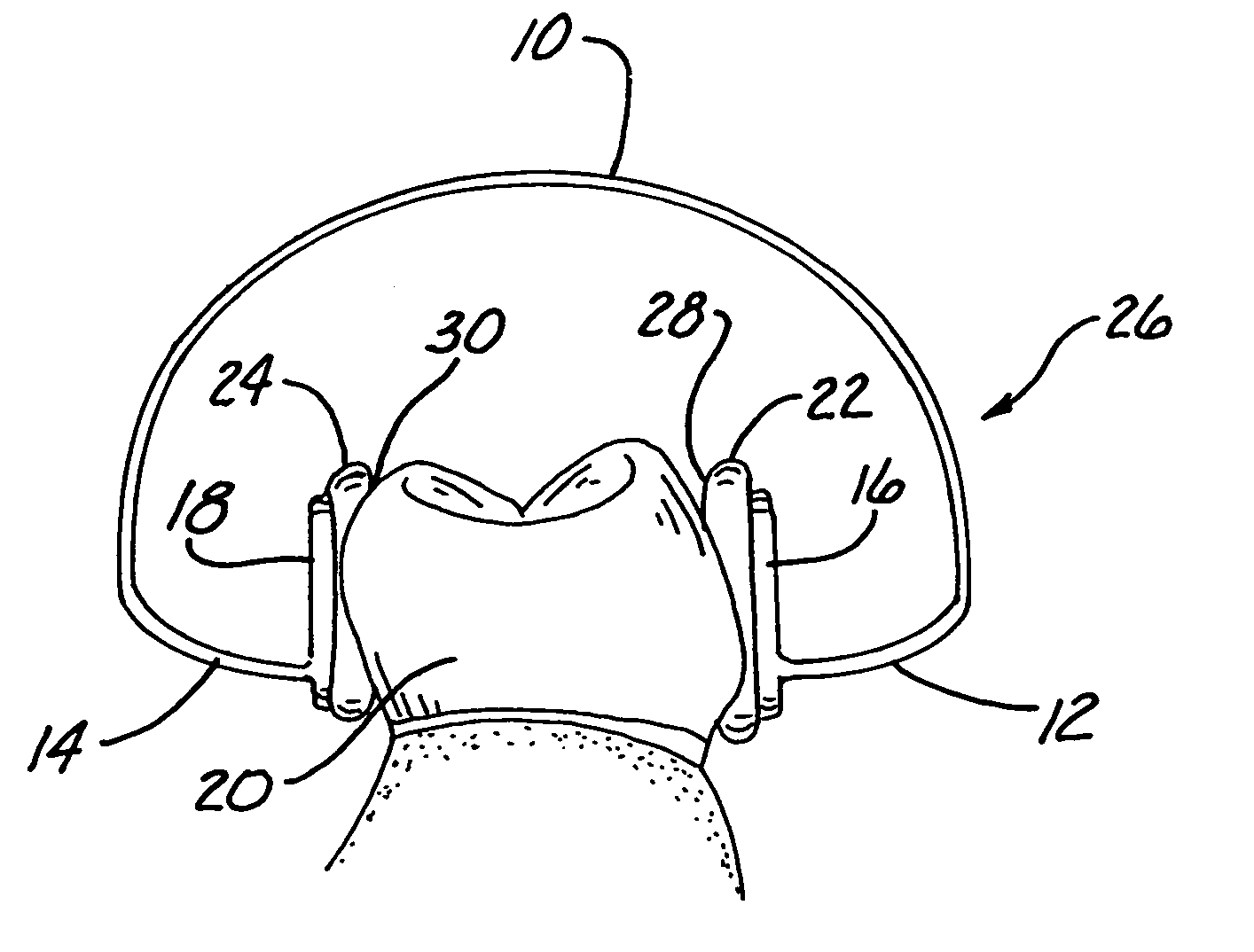
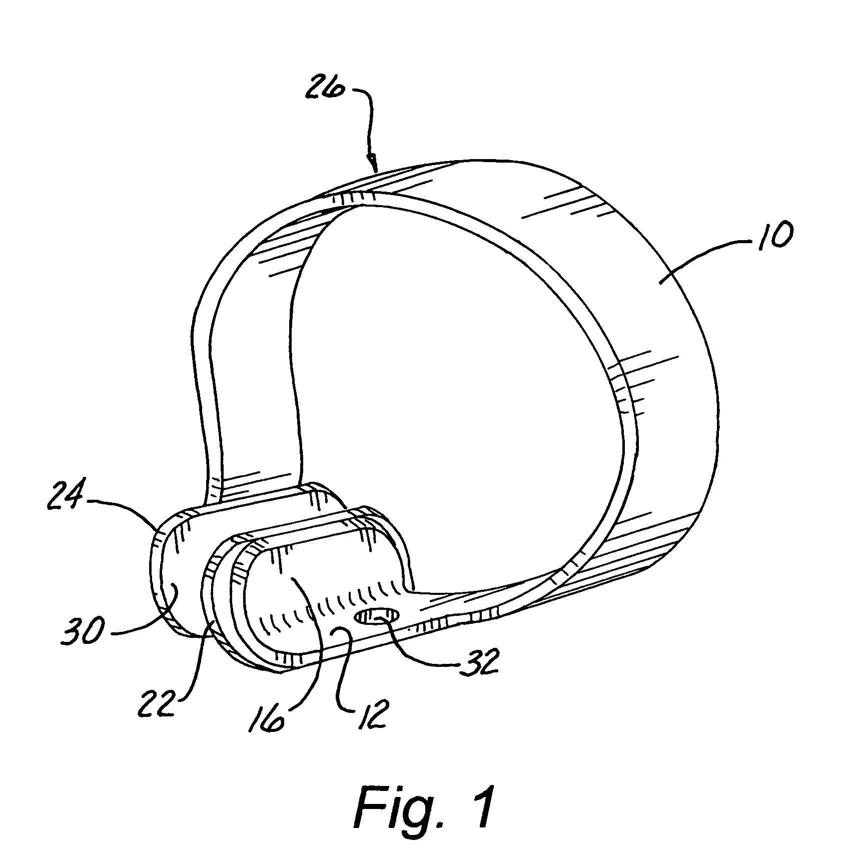
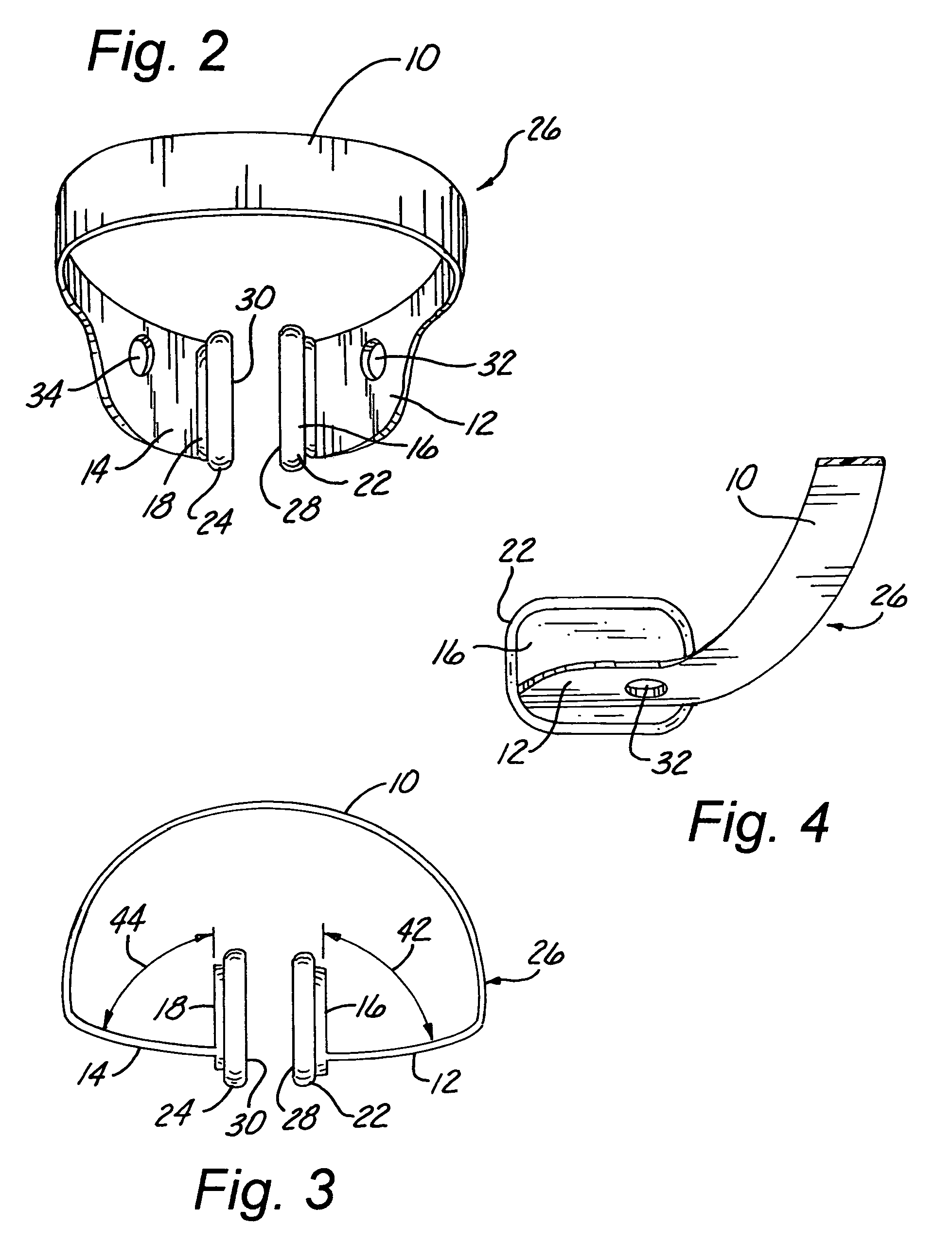
[0026]The invention consists of improved rubber dam clamps designed with broad-base flexible polymeric bonding pads, referred to as elastomeric pads, which increase the surface area of contact with a tooth, thereby increasing retentive frictional forces and providing a surface for the application of adhesives in order to be adhesively attached to a tooth during a dental procedure. Improved frictional contact and adhesive bonding result in a retaining clamp which resists dislodgement, cervical displacement, and torsional rotation, thus making the clamp far more stable and comfortable for a patient during application and far more reliable for the clincian during treatment procedures. The improvements which are a part of this disclosure are applicable to all varieties of rubber dam clamps, including conventional isolation rubber dam clamps and also general field isolation rubber dam clamps. While this disclosure focuses primarily on the clamps sharing the retentive mechanisms of improv...


PUM


Abstract

A rubber dam clamp comprising a transverse arch connecting two free ends, the two free ends having opposing retentive bonding pads for improved retention, stability, and comfort of rubber dam applications, when applied to a patient's tooth, due to the combination of increased contact surface and use of adhesives between the clamp and the tooth. Further, the invention relates to the adaptation of conventional rubber dam clamps into they type referred to above so as to create a similar combination of frictional force and use of adhesive in order to maintain the position of the clamp in dental procedures.

Description

[0001]This application claims the benefit of U.S. Provisional Application No. 60 / 327,847, filed Oct. 9, 2001.BACKGROUND OF THE INVENTION[0002]1. Field of the Invention[0003]This invention relates to the improved design of rubber dam clamps, and more particularly to improved rubber dam clamps that retain the rubber dam in the mouth of a patient during the course of dental treatment, through the use of friction and / or adhesives.[0004]2. Prior Art[0005]Rubber dam clamps are commonly known in the prior art of dentistry as devices designed to apply reciprocal mechanical forces to the sides of a tooth in order to be mechanically retained in position on that tooth to restrain a rubber dam membrane. The rubber dam, is known in the prior art of dentistry as an elastic membrane designed to isolate the dentist's operative work site from the oral environment during treatment. The rubber dam is stretched over rubber dam clamps in order to be retained in position by them during treatment. The pri...

Claims


Application Information

Patent Timeline
Patent Type & Authority Patents(United States)
IPC IPC(8): A61C5/12
CPCA61C19/004A61C5/12A61C5/80
Inventor HEASLEY, JOHN M.
Owner HEASLEY JOHN M
Why Eureka
Try Eureka