Apparatus and method for assessing the liquid flow performances through a small dispensing orifice

a technology of liquid flow and dispensing orifice, which is applied in the direction of liquid/fluent solid measurement, laboratory glassware, instruments, etc., can solve problems such as detection of plugging problems, and achieve the effect of reducing the intensity and decreasing the intensity of the optical beam

Inactive Publication Date: 2006-01-10
BIONEX SOLUTIONS
View PDF62 Cites 32 Cited by
  • Summary
  • Abstract
  • Description
  • Claims
  • Application Information

AI Technical Summary

Problems solved by technology

In the latter case, a plugging problem may be detected.

Method used


Image

  • Apparatus and method for assessing the liquid flow performances through a small dispensing orifice
  • Apparatus and method for assessing the liquid flow performances through a small dispensing orifice
  • Apparatus and method for assessing the liquid flow performances through a small dispensing orifice

Examples


Embodiment Construction

[0041]While the present invention will be described with reference to a few specific embodiments, the description is illustrative of the invention and is not to be construed as limiting the invention. Various modifications to the present invention can be made to the preferred embodiments by those skilled in the art without departing from the true spirit and scope of the invention as defined by the appended claims. It will be noted here that for a better understanding, like components are designated by like reference numerals throughout the various figures.

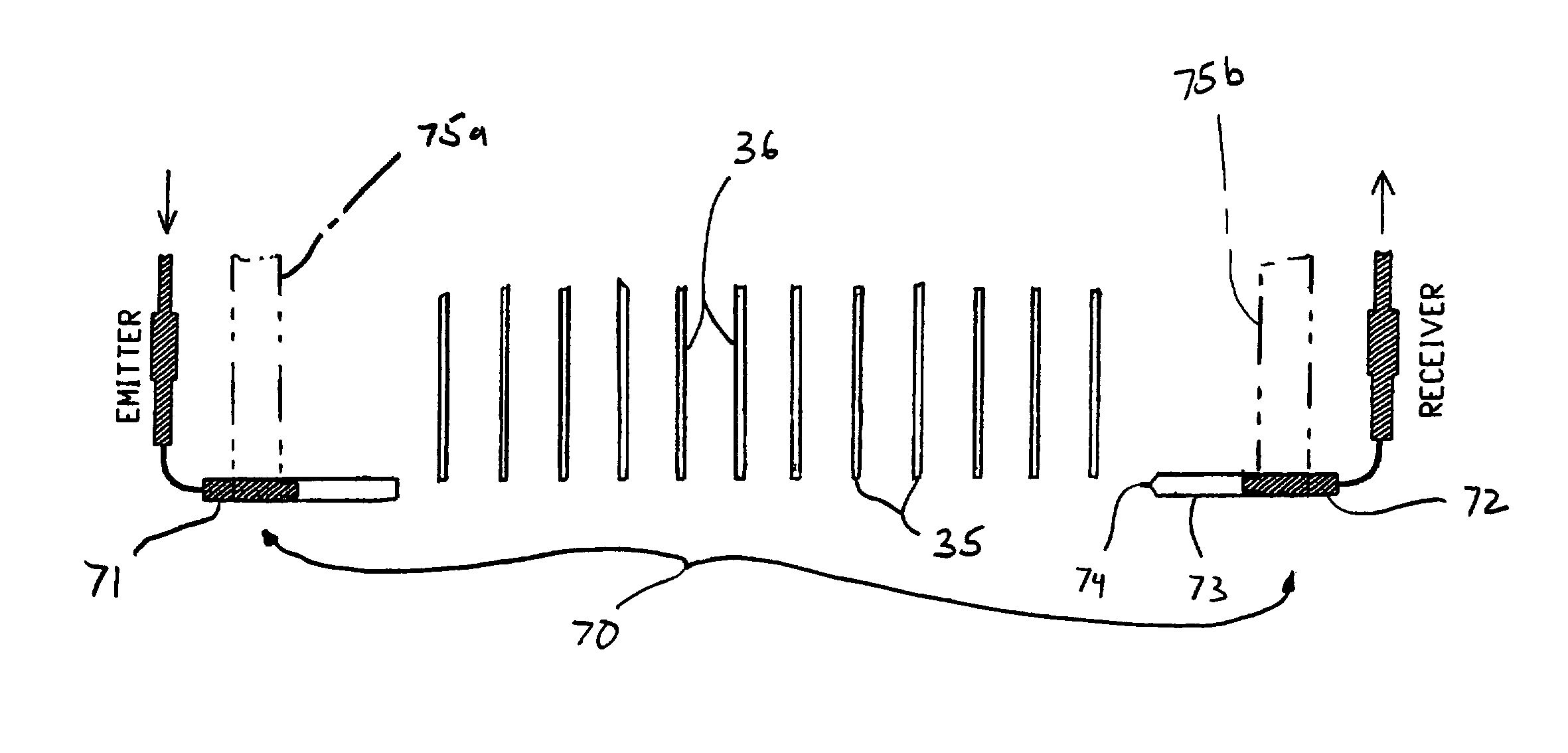
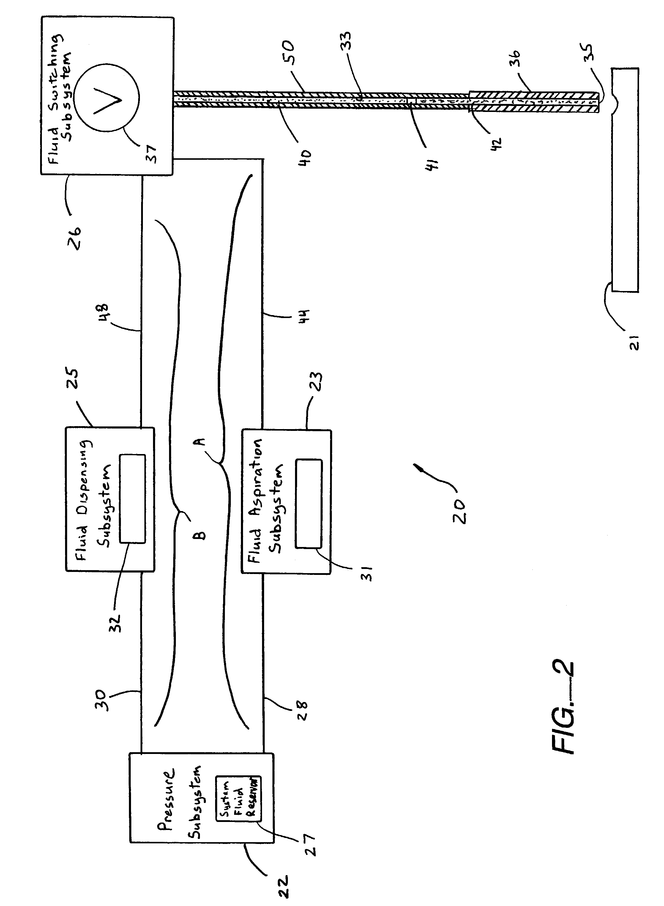
[0042]Referring now to FIG. 2, a non-contact liquid handling method and system, generally designated 20, is provided which is capable of precise low volume, liquid dispensing onto a target or destination substrate surface 21. Broadly, in one specific embodiment, the liquid handling system 20 includes a pressure subsystem 22, a fluid aspiration (input) subsystem 23, a fluid dispensing (output) subsystem 25 and a fluid switching subs...


PUM

PropertyMeasurementUnit
diameteraaaaaaaaaa
diameteraaaaaaaaaa
volumesaaaaaaaaaa

Abstract

A universal calibration apparatus and method to estimate the dispense output from a low volume, non-contact, liquid dispensing systems that may be applied for every hardware configuration (e.g., tube length, orifice diameter, tip design, etc), reagent solution property and environmental condition. This same calibration technique is applied to calibrate or tune these non-contact liquid dispensing systems to dispense desired volumes (in the range of about 0.050 μL to 50 μL), irrespective of the hardware configuration or the solution properties. That is, the calibration technique is not dependent on any variables, but the result (the actual dispense volume) is dependant on the variable mentioned. By actuating selected pulse widths, and measuring the resulting volume, a Calibration Profile can be generated correlating the liquid volume dispensed from the orifice to the respective pulse width of the dispensing valve thereof through calibration points. In particular, one is selected to deliver a first volume of liquid that is less than a lower base pulse width correlating to the lowest volume of the selected range of volumes of liquid, while a second pulse width is selected to deliver a second volume of liquid dispensed that is greater than an upper ceiling pulse width correlating to the highest volume of the selected range of volumes of liquid. Intermediary pulse widths are also applied, each selected to deliver a different, spaced-apart, respective intermediary low volumes of liquid dispensed from the dispensing orifice between the first volume and the second volume. Thus, applying the Calibration Profile, the pulse widths correlating to the one or more targeted discrete volumes for liquid dispensing can be extrapolated.

Description

RELATED APPLICATION DATA[0001]The present application claims priority under 35 U.S.C. §119 to U.S. Provisional Application Ser. No. 60 / 351,858, naming Johnson et al. inventors, and filed Jan. 25, 2002, and entitled METHODS FOR HIGH-PERFORMANCE, LOW-VOLUME DISPENSING, the entirety of which is incorporated herein by reference in its entirety for all purposes.TECHNICAL FIELD[0002]The present invention relates to methods and apparatus for liquid handling, and more particularly, relates to methods and apparatus for non-contact, high performance, relatively low volume liquid dispensing.BACKGROUND ART[0003]Advances in Life Sciences, particularly in genomics and proteomics, have greatly increased the potential number of reactions and analyses that must be performed by the biotechnology and pharmaceutical industries. An estimated 30 million tests are required to screen a typical pharmaceutical company's compound library against target receptors. The typical number of tests will increase dram...

Claims


Application Information

Patent Timeline
Patent Type & Authority Patents(United States)
IPC IPC(8): G01F25/00G01N37/00B01L3/02G01N35/00G01N35/10
CPCB01L3/021G01N35/00594G01N35/1016G01N35/1065B01L3/0268Y10T436/15B01L2200/143B01L2200/148B01L2300/14B01L2400/02B01L2400/0487B01L2400/06B01L2400/0633B01L2400/0666G01N35/00712G01N35/1002G01N2035/00237G01N2035/1041G01N2035/1044Y10T436/2575Y10T137/3003
Inventor JOHNSON, JAMES E.PICHA, NEIL R.STORMS, CRAIG M.MARTIN, DAVID A.
Owner BIONEX SOLUTIONS
Why Eureka
Try Eureka