Needle safety device

a safety device and needle technology, applied in the field of needle assembly, can solve the problem that the needle cannula cannot be re-exposed after shielding

Active Publication Date: 2006-01-10
BECTON DICKINSON & CO
View PDF61 Cites 106 Cited by
  • Summary
  • Abstract
  • Description
  • Claims
  • Application Information

AI Technical Summary

Benefits of technology

[0013]Additionally, in some cases, practitioners may be rushing and forget to operate the safety shield. Other situations arise where the patient moves suddenly or unexpectedly. Thus the needle cannula may inadvertently be pulled out of the vein and exposed with no time for the phlebotomist to initiate safety shielding. These weaknesses are not addressed adequately in prior art devices.

Problems solved by technology

Thus, the needle cannula cannot be re-exposed after shielding.

Method used


Image

  • Needle safety device
  • Needle safety device
  • Needle safety device

Examples


Embodiment Construction

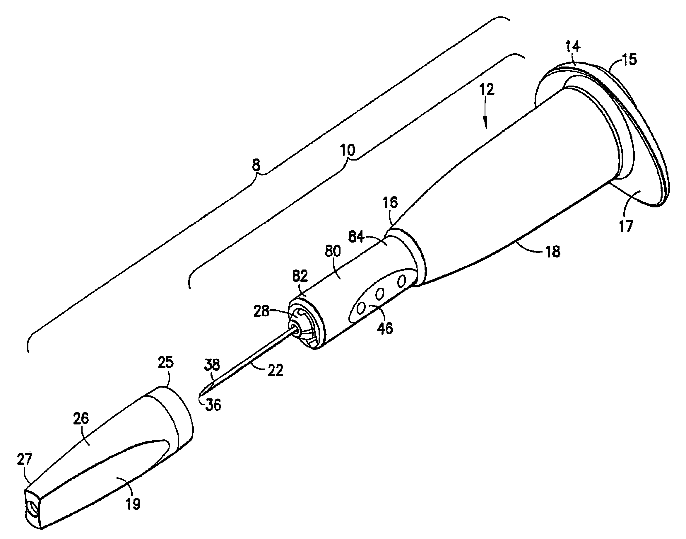
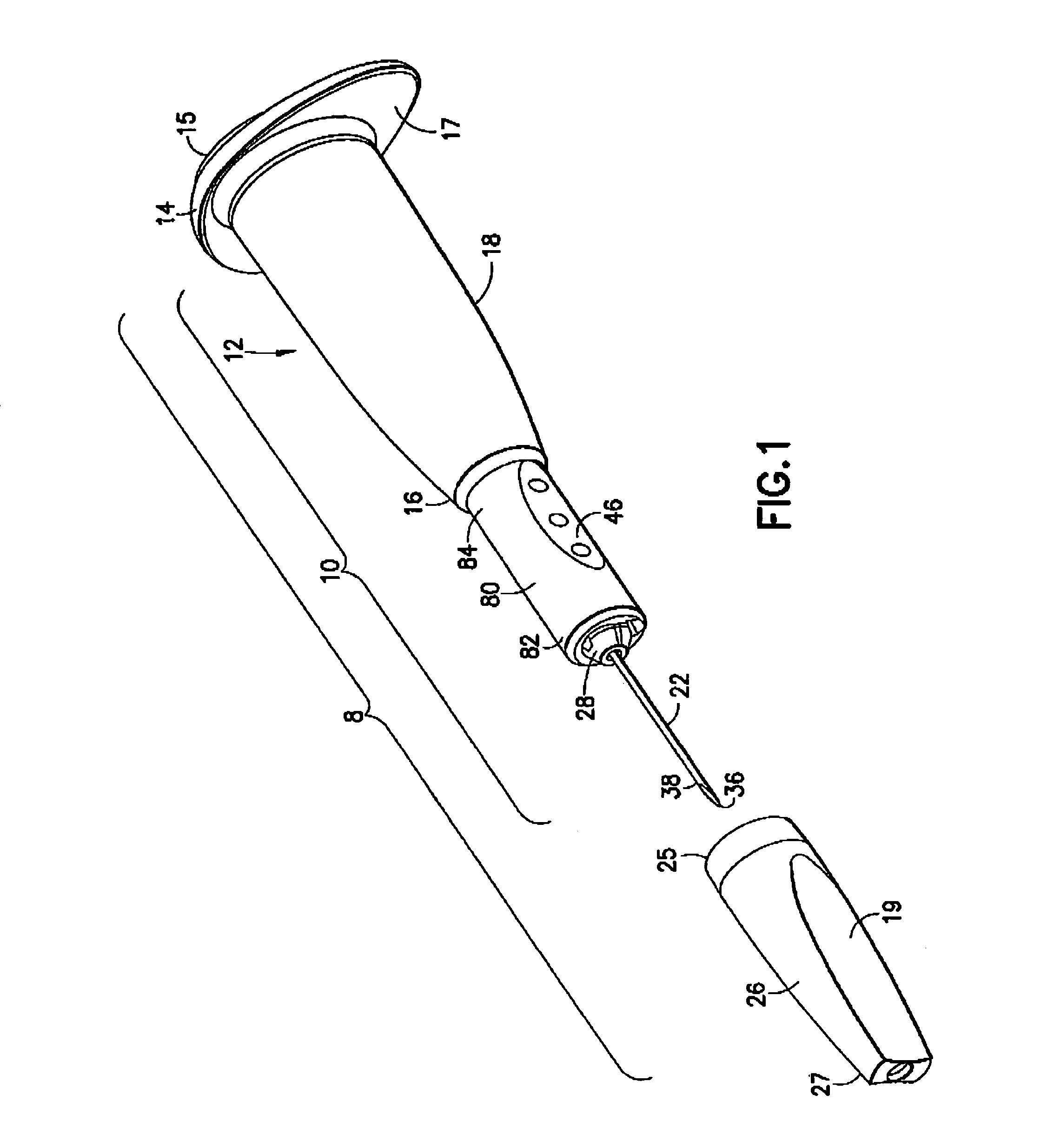
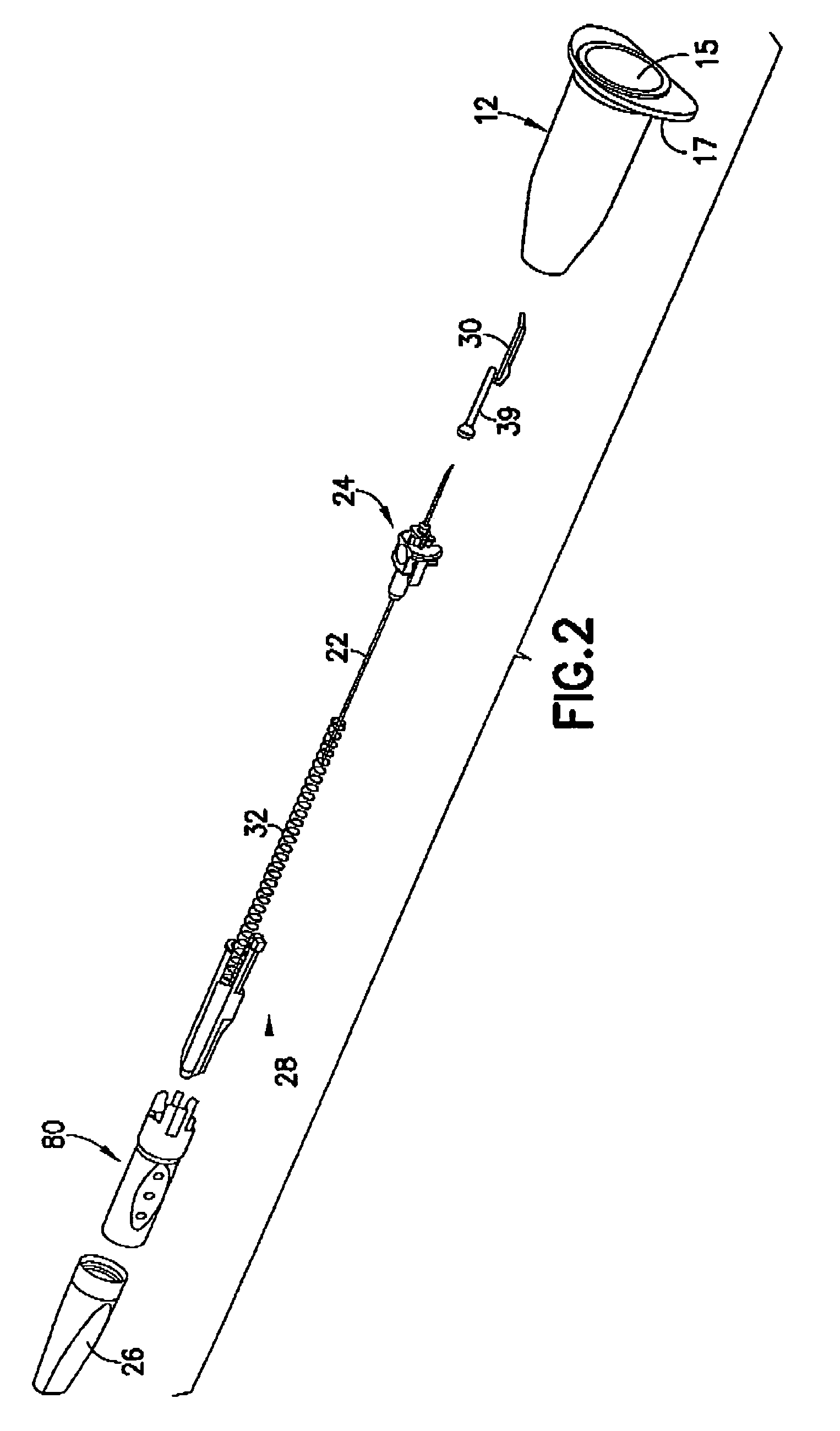
[0060]The needle assembly 10 of the present invention is shown in FIGS. 1–7 and 11–20. It will be noted that the term “distal” as used herein refers to the end of the needle assembly that punctures the patient's skin while “proximal” means the end of the needle assembly that punctures an evacuated container. Needle assembly 10 is mounted to a needle holder 12, as shown in FIGS. 1, 3, and 4. Needle holder 12 has a proximal end 14, a distal end 16 and a tubular sidewall 18 extending between ends 14 and 16. Proximal end 14 of needle holder 12 is widely open and is adapted to receive a blood collection tube 20 as shown in FIGS. 17, 19A–19D, and 20A–20D. However, proximal end 14 of holder 12 may have a removable seal or cap 15 for sterility. Proximal end 14 of holder 12 also has a radially aligned finger flange 17 to facilitate manipulation of holder 12. Flange 17 is non-circular to prevent holder 12 from rolling. Flange 17 preferably has a linear edge to provide a clear indication of th...


PUM


Abstract

A needle assembly includes a needle and a hub mounted to each other. The hub includes a sidewall spaced outwardly from the needle cannula and extending to a distal position between the opposed ends of the needle cannula. A housing integral with the hub defines a sidewall to partially confine a safety shield. The safety shield is slidably disposed about the needle cannula and releasably retained in a proximal position and can be moved to a distal position where the safety shield completely surrounds that portion of the needle hub projecting distally from the hub. The needle assembly includes a spring for propelling the safety shield to the distal position and a latch for releasing the safety shield from the proximal position. The latch may be passively activated by normal usage of the medical implement to which the needle assembly is mounted or alternately activated manually.

Description

RELATED APPLICATION[0001]This application is a non-provisional of U.S. Provisional Patent Appl. No. 60 / 354,202, filed Nov. 13, 2001.BACKGROUND OF THE INVENTION[0002]1. Field of the Invention[0003]The present invention relates to a needle assembly having a needle cannula, a hub to which the needle cannula is mounted and a safety shield that can be telescoped from a proximal position where the needle cannula is exposed to a distal position where the needle cannula is safely shielded.[0004]2. Description of the Related Art[0005]A typical needle assembly includes a needle cannula having a proximal end, a pointed distal end and a lumen extending between the ends. A thermoplastic hub is mounted securely to the needle cannula at a location spaced from the distal end. The hub is provided with external threads or other surface configurations for removably mounting the prior art needle cannula on another structure. Some needle assemblies are used for drawing a sample of blood or other body fl...

Claims


Application Information

Patent Timeline
Patent Type & Authority Patents(United States)
IPC IPC(8): A61M5/00A61B5/15A61B5/154A61M5/178A61M5/32
CPCA61B5/1438A61M5/5086A61M5/3243A61M2205/583A61M5/3257A61B5/15003A61B5/150259A61B5/150389A61B5/150496A61B5/150572A61B5/150587A61B5/150648A61B5/150656A61B5/150717A61B5/150732A61B5/150824A61B5/154
Inventor NEWBY, C. MARKBENNETT, MICHAELCONWAY, HUGH T.WILKINSON, BRADLEY M.HITCHINGS, JOHN
Owner BECTON DICKINSON & CO
Why Eureka
Try Eureka