Variable directional capacitor microphone comprising elastic acoustic resisting member

a capacitor and capacitor microphone technology, applied in the direction of electrical transducers, transducer types, piezoelectric/electrostrictive transducers, etc., can solve the problems of not being able to achieve expected characteristics, and not being able to guarantee that the adjustment of acoustic resistance is completed only once, so as to prevent sound leakage and increase the degree of freedom of compressed volume

Inactive Publication Date: 2006-01-10
AUDIO-TECHNICA
View PDF4 Cites 18 Cited by
  • Summary
  • Abstract
  • Description
  • Claims
  • Application Information

AI Technical Summary

Benefits of technology

[0017]In this invention, it is preferable that an elastic gasket formed with rubber material or the like is disposed around the circumference of the acoustic resisting member installed between the first and the second pedestals to prevent sound leakage through the acoustic resisting member.

Problems solved by technology

However, no expected characteristics may be obtained after the capacitor elements have been combined.
However, there is no guarantee that the adjustment of the acoustic resistance is completed only once.

Method used


Image

  • Variable directional capacitor microphone comprising elastic acoustic resisting member
  • Variable directional capacitor microphone comprising elastic acoustic resisting member
  • Variable directional capacitor microphone comprising elastic acoustic resisting member

Examples


Embodiment Construction

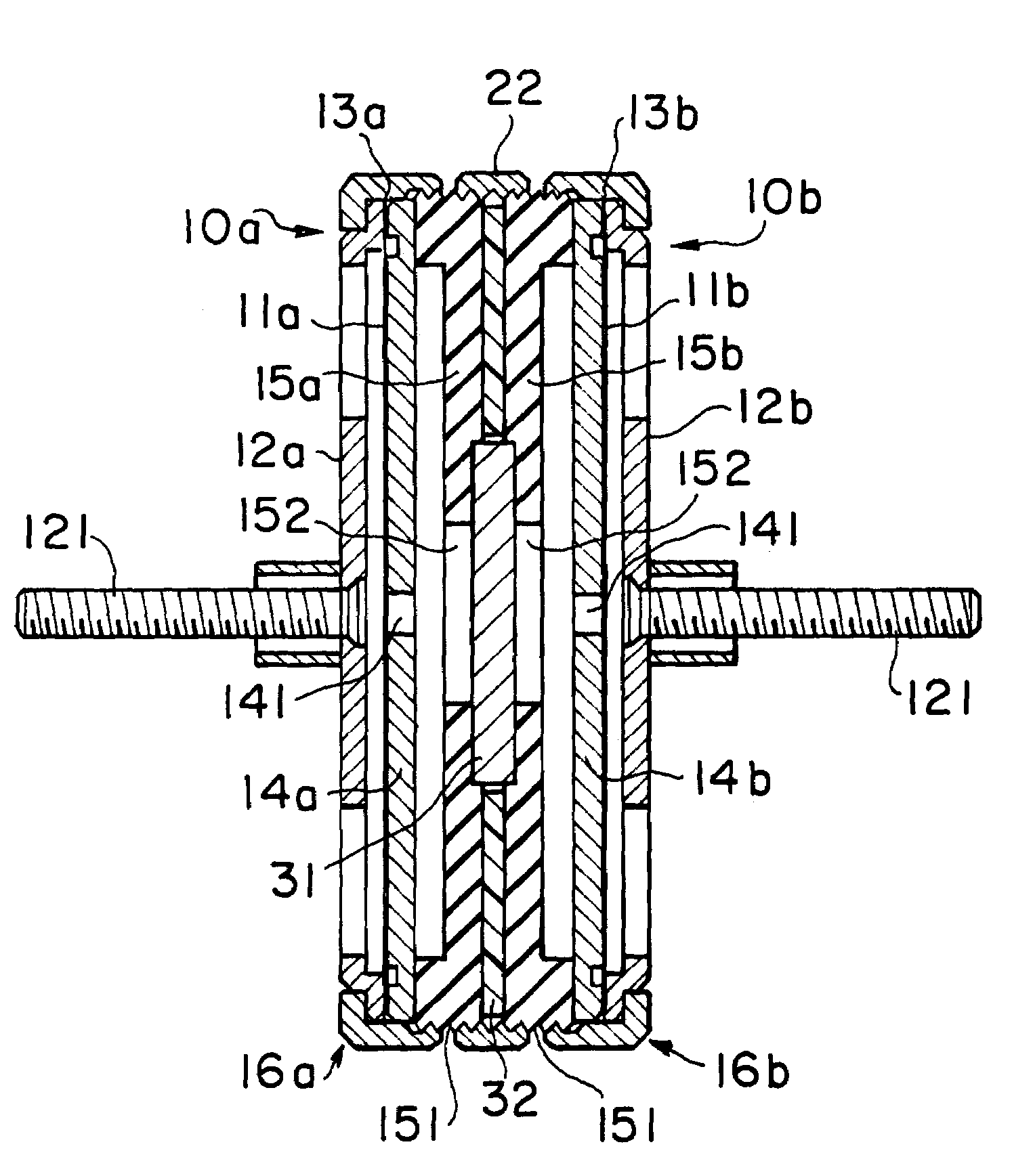
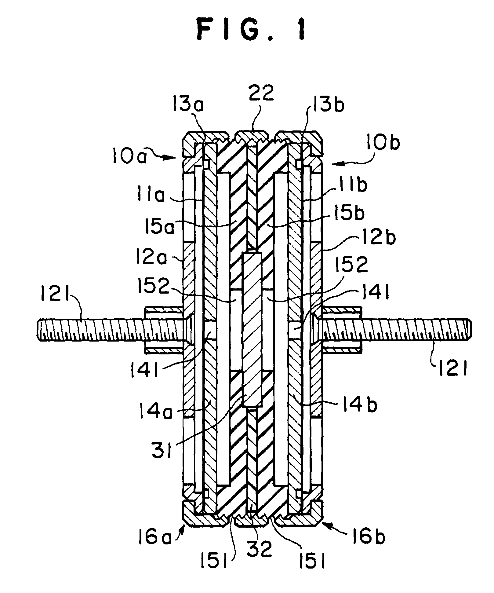
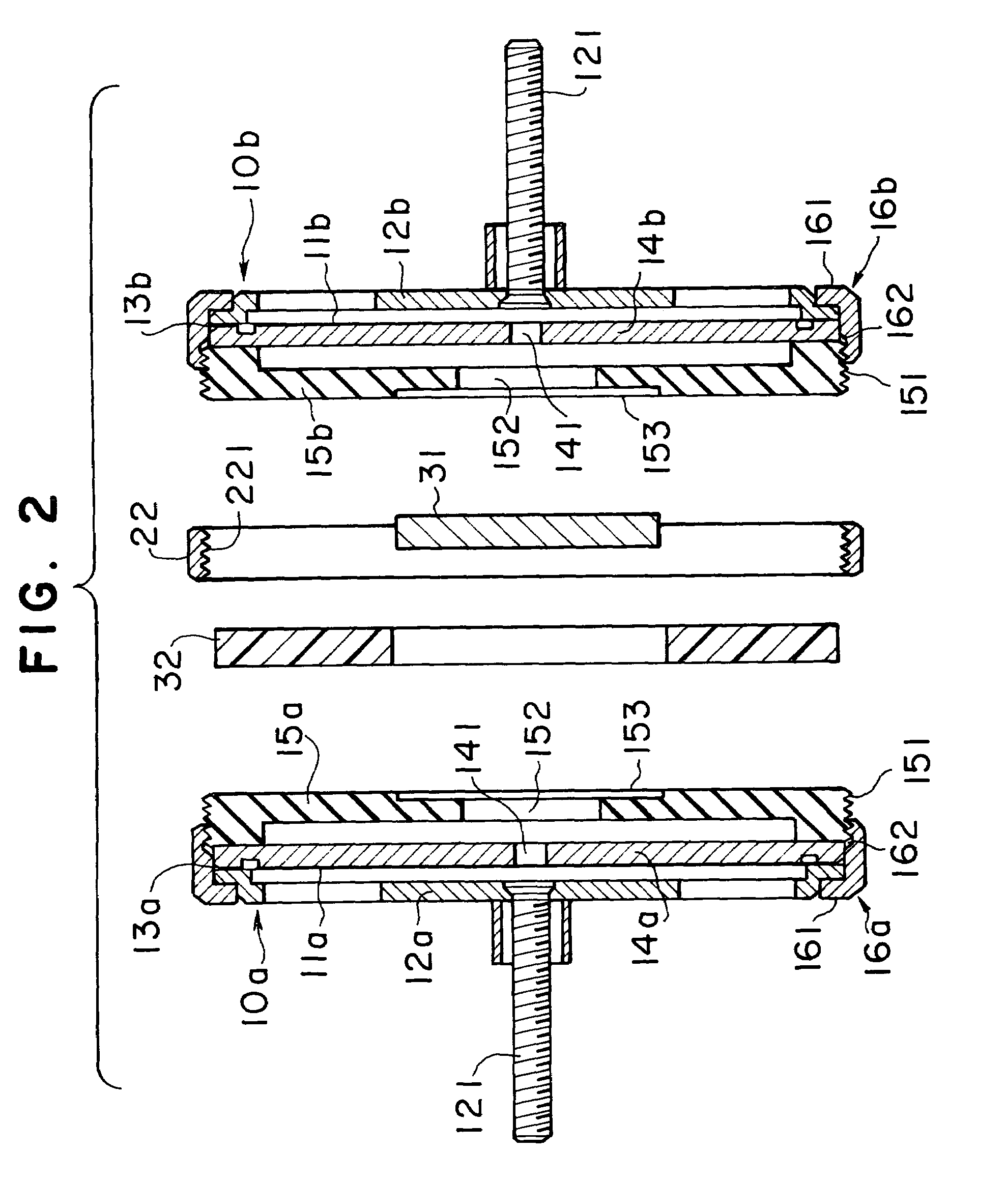
[0025]Referring to FIGS. 1 and 2, an embodiment of the present invention will be described. The invention is not restricted to this embodiment. FIG. 1 is a cross sectional view of a variable directional capacitor microphone which has been assembled embodying the present invention. FIG. 1 corresponds to FIG. 3 described before. FIG. 2 is an exploded cross sectional view of the variable directional capacitor corresponding to FIG. 4 described before. In the explanation of the embodiment, attached to the constituent elements which are the same or are deemed to be the same as that of a prior art are the same reference numerals and symbols as that of the prior art.

[0026]As the basic structure, the variable directional capacitor microphone of the invention includes a first and a second capacitor elements with the both elements combined through a connecting ring 22. Since the first and the second capacitor elements have the same structure as described above, hereinafter, the first capacitor...


PUM


Abstract

The present invention includes a variable directional capacitor microphone in which two capacitor elements are combined. Each of the capacitor elements includes a vibrating plate and a fixed electrode, and an acoustic resistance can be adjusted in the state that the microphone has been assembled. The variable directional capacitor microphone of this invention includes capacitor elements 10a, 10b. In each of the capacitor elements 10a, 10b, each of vibrating plate supporting members 12a, 12b, each of spacer rings 13a, 13b, each of fixed electrodes 14a, 14b having through holes 141 and each of pedestals 15a, 15b having a through hole in each center of the pedestals are assembled in this order, respectively, in each of ring-shaped cases 16a, 16b. Each of vibrating plates 11a, 11b is strained and fixed on each of vibrating plate supporting members 12a, 12b, respectively. The capacitor elements 10a, 10b are combined through a connecting ring 22 having female screw threads 221 with the pedestal 15a, 15b facing back-to-back. An elastic acoustic resisting member 31 is disposed between the pedestals 15a, 15b. The acoustic resistance of the acoustic resisting member 31 can be adjusted with the lengths of thread engagement of the pedestals 15a, 15b with the connecting ring 22.

Description

FIELD OF THE INVENTION[0001]The present invention relates to a variable directional microphone. More particularly, the invention relates to the variable directional microphone having two capacitor elements each of which includes a vibrating plate and a fixed electrode with the both capacitor elements combined in the microphone.BACKGROUND OF THE INVENTION[0002]Japanese Patent registration No. 3299829 discloses a variable directional capacitor microphone including two capacitor elements each of which has a vibrating plate and a fixed electrode. The two capacitor elements are combined as to supply a part of sound pressure impressed to a vibrating plate of the one capacitor element (a rear capacitor element) to the back side of a vibrating plate of the other capacitor element (a front capacitor element). The structure will be described referring to FIGS. 3 and 4. FIG. 3 is a cross sectional view of the variable directional capacitor microphone which has been assembled and FIG. 4 is an e...

Claims


Application Information

Patent Timeline
Patent Type & Authority Patents(United States)
IPC IPC(8): H04R25/00H04R19/00H04R1/38
CPCH04R1/38
Inventor AKINO, HIROSHI
Owner AUDIO-TECHNICA
Why Eureka
Try Eureka