Microphone package, lead frame, mold substrate, and mounting structure therefor

a technology for mold substrates and microphone packages, which is applied in the direction of piezoelectric/electrostrictive transducers, mouthpiece/microphone attachments, transducer types, etc., can solve the problems of pushed up manufacturing costs and relatively expensive multi-layered wiring substrates used in the housing of microphone packages, so as to avoid sound leakage, facilitate manufacturing of microphone packages, and low cost

Inactive Publication Date: 2009-07-09
YAMAHA CORP
View PDF5 Cites 7 Cited by
  • Summary
  • Abstract
  • Description
  • Claims
  • Application Information

AI Technical Summary

Benefits of technology

[0027]In short, since the distal surface of the cylindrical projection is integrally formed with the stage in the surrounding area of the sound hole so as to avoid sound leakage, it is possible to easily manufacture the microphone package at low cost and avoid sound leakage.

Problems solved by technology

Generally speaking, multilayered wiring substrates for use in housings of microphone packages are relatively costly.
This is very troublesome in manufacturing microphone packages, thus pushing up the manufacturing costs.

Method used


Image

  • Microphone package, lead frame, mold substrate, and mounting structure therefor
  • Microphone package, lead frame, mold substrate, and mounting structure therefor
  • Microphone package, lead frame, mold substrate, and mounting structure therefor

Examples


first embodiment

1. First Embodiment

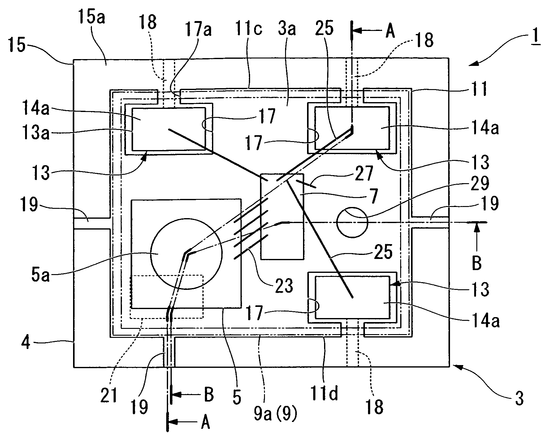
[0051]A microphone package 1 according to a first embodiment of the present invention will be described with reference to FIGS. 1 to 13. The microphone package 1 is used to detect pressure variations such as sounds generated in the external space and is formed as a surface mount package which is manufactured using a lead frame in accordance with the resin mold technology.

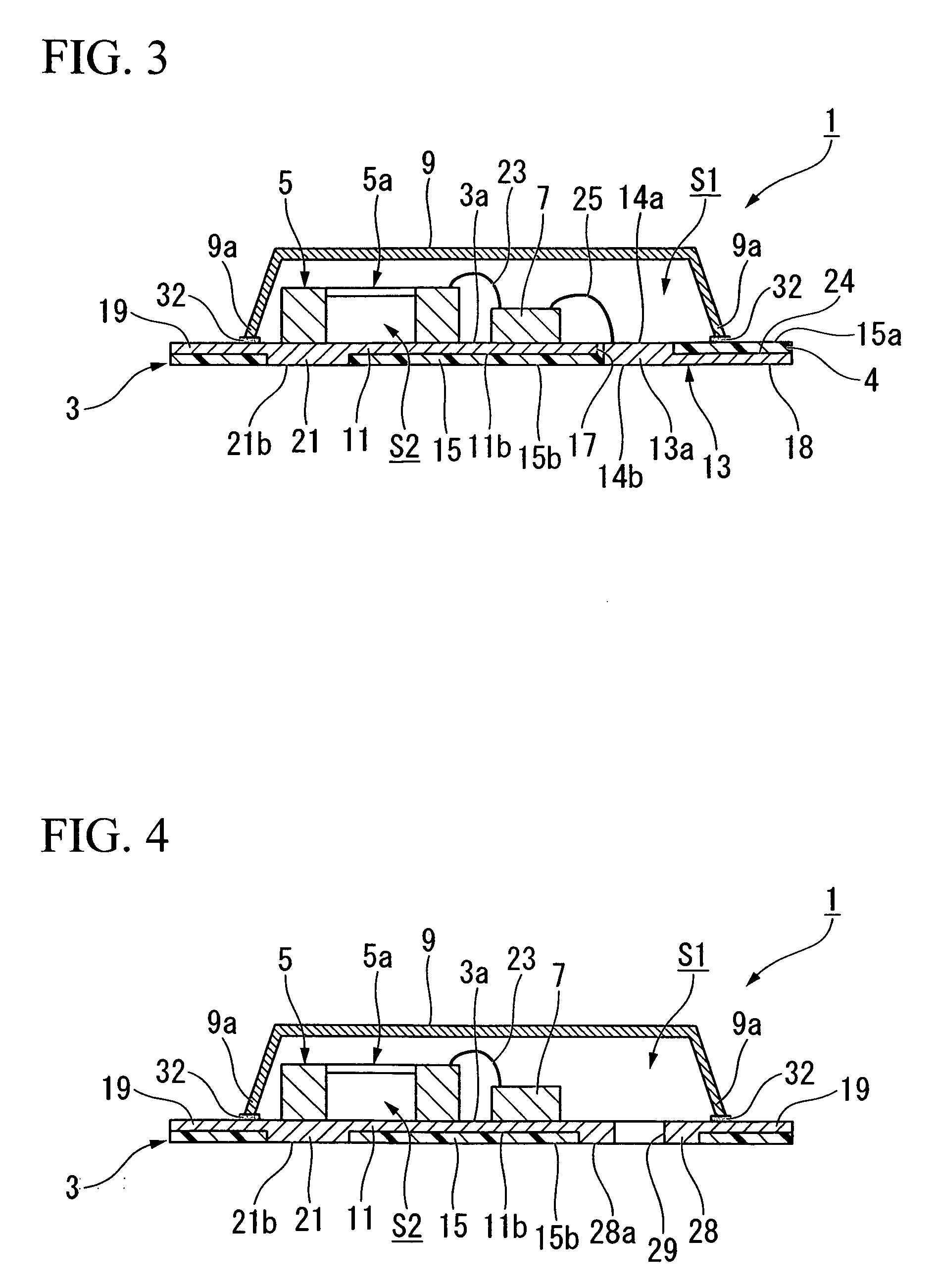
[0052]As shown in FIGS. 1 to 4, the microphone package 1 is constituted of a mold substrate 3 having a rectangular plate shape in plan view, a microphone chip (or a semiconductor chip) 5 and a companion chip 7 both mounted on a surface 3a of the mold substrate 3, and a cover 9 which is combined with the mold substrate 3 so as to cover the microphone chip 5 and the companion chip 7.

[0053]The mold substrate 3 is constituted of a stage 11 having a rectangular plate shape for forming the surface 3a of the mold substrate 3, a plurality of leads (e.g. three lead terminals) 13 for electrically connecting...

second embodiment

2. Second Embodiment

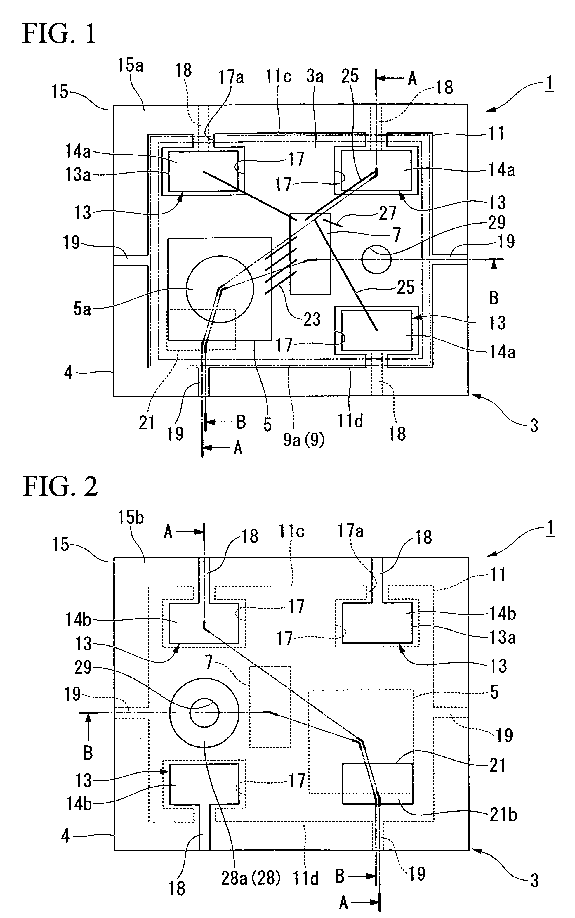
[0112]Next, a microphone package 51 according to a second embodiment of the present invention will be described with reference to FIGS. 17 to 19, wherein parts identical to those of the microphone package 1 of the first embodiment are designated by the same reference numerals; hence, duplicate descriptions thereof are simplified or omitted.

[0113]Similar to the microphone package 1, the microphone package 51 shown in FIGS. 17 to 19 has a mold substrate 53 having a rectangular plate shape in plan view. The mold substrate 53 includes a stage 55 (whose surface forms a surface 53a of the mold substrate 53), a plurality of lead terminals 57 which are electrically connected with the microphone chip 5 and the companion chip 7, and a resin mold (or an insulating member) for sealing the stage 55 and the lead terminals 57 in an electrically insulating manner.

[0114]The surface 53a of the stage 55 is exposed from a surface 59a of the resin mold 59 so as to form the same plane...


PUM


Abstract

A microphone package is constituted of a cover and a mold substrate that is formed in accordance with the resin mold technology so as to form a cavity for embracing a microphone chip. The mold substrate is constituted of a stage having conductivity and a rectangular shape for mounting a microphone chip thereon, a plurality of lead terminals having conductivity and electrically connected to the microphone chip, and a resin mold for electrically insulating the stage from the lead terminals. A sound hole is formed in the mold substrate by use of a cylindrical projection which projects from the backside of the stage and whose distal surface is exposed from the backside of the mold substrate. When the microphone package is mounted on the mounting surface of an external substrate, it is possible to prevent sound from being leaked via gaps therebetween.

Description

BACKGROUND OF THE INVENTION[0001]1. Field of the Invention[0002]The present invention relates to microphone packages, lead frames, and mold substrates for encapsulating microphone chips.[0003]The present invention also relates to mounting structures adapted to microphone packages.[0004]The present application claims priority on Japanese Patent Application No. 2008-2411, the content of which is incorporated herein by reference.[0005]2. Description of the Related Art[0006]Conventionally, various technologies regarding miniature condenser microphones and packages have been developed and disclosed in various documents such as Patent Documents 1 and 2.[0007]Patent Document 1: Japanese Patent Application Publication No.[0008]Patent Document 2: U.S. Pat. No. 6,781,231[0009]Patent Document 1 teaches a microphone package in which a microphone chip for detecting sound is installed in a housing having a sound hole and a hollow cavity. The housing is constituted of a multilayered wiring substra...

Claims


Application Information

Patent Timeline
Patent Type & Authority Applications(United States)
IPC IPC(8): H04R1/02
CPCH04R1/08H01L2224/48091H01L2224/48137H01L2924/3025H01L2924/00014H01L2924/00H05K1/02H04R19/04
Inventor SHIRASAKA, KENICHI
Owner YAMAHA CORP
Why Eureka
Try Eureka