System and method for on-the-fly eccentricity recognition

a technology of eccentricity and recognition system, applied in the field of system and method for detecting eccentricities of substrates, can solve the problems of undesirable delays, undesirable eccentricity or misalignment of robots, and increase the overall complexity and cost of the system, and achieve undesirable delays

Active Publication Date: 2006-01-24
BOOKS AUTOMATION US LLC
View PDF18 Cites 414 Cited by
  • Summary
  • Abstract
  • Description
  • Claims
  • Application Information

AI Technical Summary

Problems solved by technology

As a result of limited, but not negligible, motion of the substrates in the cassettes during transportation, the robot may pick the substrate with undesirable eccentricity or misalignment.
This approach introduces undesirable delays associated with the additional pick-place operations and with the edge-scanning process, all of which are executed sequentially rather than in an on-the-fly manner.
It also undesirably increases the overall complexity and cost of the system.
However, the mass and complexity of the moving components of the robot arm increases undesirably, which results in limited speed, compromised reliability and a higher cost.
However, one disadvantage of this method is that it requires an array of multiple sensors.

Method used


Image

  • System and method for on-the-fly eccentricity recognition
  • System and method for on-the-fly eccentricity recognition
  • System and method for on-the-fly eccentricity recognition

Examples


Embodiment Construction

)

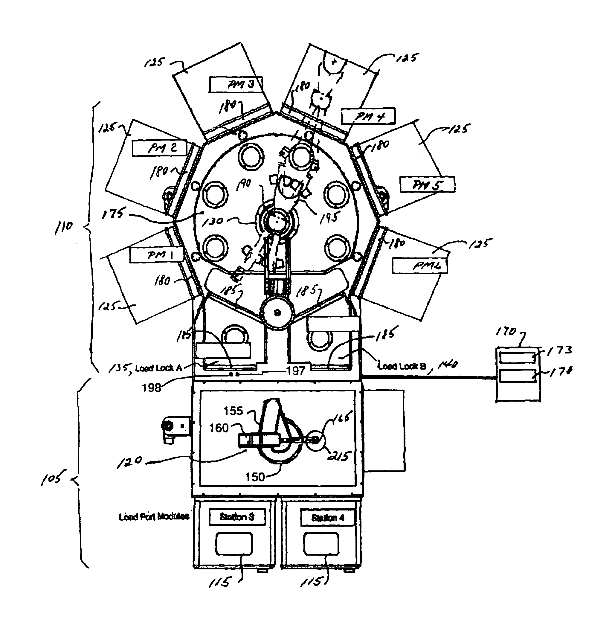
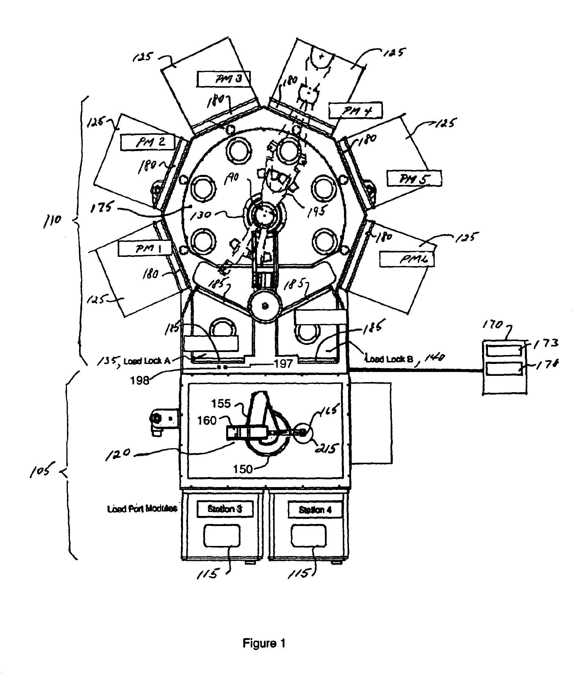
[0031]Referring to FIG. 1, a plan view of a system, shown in this example as a substrate processing apparatus 100, incorporating features of the present invention is illustrated. Although the present invention will be described with reference to the embodiment shown in the drawings, it should be understood that the present invention can be embodied in many alternate forms of embodiments. In addition, any suitable size, shape or type of elements or materials could be used.

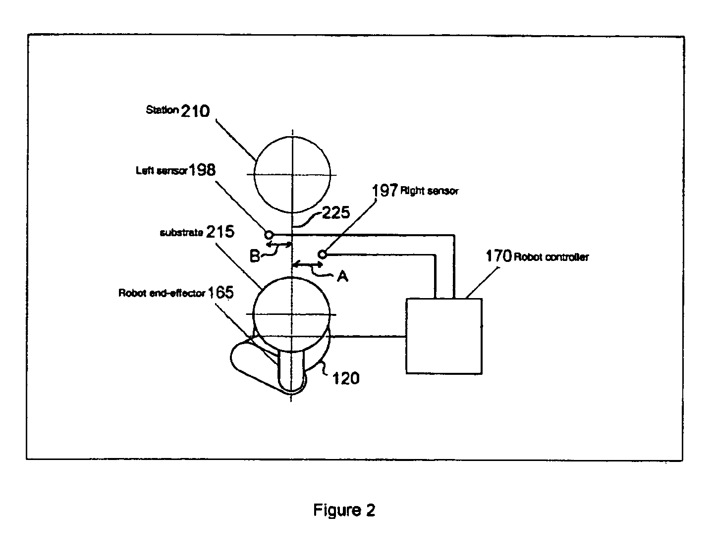
[0032]The present invention includes a substrate transport capability shown in FIG. 1 as one or more robot arms 120, 130 and a sensing capability shown in FIG. 1 as sensors 197, 198 and controller 170. The substrate transport capability 120, 130 and the sensing capability 197, 198 operate to provide for on-the-fly determination of eccentricity or misalignment of a substrate.

[0033]For purposes of this invention a substrate may be for example, a semiconductor wafer, any other type of substrate suitable for processing...


PUM

PropertyMeasurementUnit
distanceaaaaaaaaaa
angleaaaaaaaaaa
angleaaaaaaaaaa

Abstract

A method of substrate eccentricity detection includes includes determining at least three positions on a perimeter of a first substrate, grouping the at least three perimeter positions to define one or more circles, estimating a location of a center of the first substrate as the location of a center of a predetermined circle approximated from the at least three perimeter positions, and determining an eccentricity vector as a difference between the estimated location and a reference position on a substrate transport mechanism on which the first substrate rests.

Description

[0001]This application claims the benefit of U.S. Provisional Application No. 60 / 435,552, filed Dec. 20, 2002.BACKGROUND OF THE INVENTION[0002]1. Field of the Invention[0003]The present invention relates to a system and method for substrate detection and, more particularly, to substrate eccentricity detection.[0004]2. Brief Description of Related Developments[0005]Typical manufacturing processes for semiconductor integrated circuits may utilize robotic manipulators to cycle substrates, for example, circular silicon wafers, through pre-determined sequences of operations in fully automated processing equipment. Substrates may be delivered to the substrate processing equipment, also referred to as a tool, in standard transportation cassettes which house a batch of substrates stored in horizontal slots. Individual substrates may then be transferred from the cassettes by a specialized pick-place robot which may be integrated into the tool. Typically, the robot holds a substrate by means ...

Claims


Application Information

Patent Timeline
Patent Type & Authority Patents(United States)
IPC IPC(8): G06F15/00G03F7/20G03F9/00H01L21/00H01L21/68H01L21/687
CPCG03F7/7075G03F9/7003H01L21/68707H01L21/681H01L21/67265
Inventor HOSEK, MARTIN
Owner BOOKS AUTOMATION US LLC
Why Eureka
Try Eureka