Combined sensor

a sensor and combined technology, applied in the field of combined sensors, can solve the problems of false alarm, inability to set the beam position on the ground near the outer edge of the target, and inability to detect accurately, so as to avoid false alarm, enhance the reliability of the sensor, and avoid false alarm

Inactive Publication Date: 2006-01-31
OPTEX CO LTD
View PDF4 Cites 15 Cited by
  • Summary
  • Abstract
  • Description
  • Claims
  • Application Information

AI Technical Summary

Benefits of technology

[0011]As means for solving the problem according to the present invention to achieve the above object, a combined sensor provided with two-frequency MW and infrared sensors is capable of avoiding false alarm even in the event of a deviation of the infrared sensor's detection area due to sensor mounting error or other causes by properly setting a frequency difference between two microwaves sent by the MW sensor.
[0016]Specific description will be given with reference to FIG. 5. For instance, if the phase difference between IF signals is 90° (π / 2), two points (α, β in the figure) are obtained as the distance to the object in consideration of the aforementioned “aliasing error.” However, a frequency difference is set between two microwaves in the present means for solving the problem, thus eliminating the need to consider the phase difference between IF signals (phase difference derived from the existence of an object at a location β) when there is an object at a farther distance than the maximum detection distance (distance Rpir2 in the figure) in the event of a deviation of the detection area attributable to infrared sensor mounting error. The reason is that the infrared sensor does not issue an alarm in such a case (the infrared sensor does not detect an object at this position even in the event of the maximum infrared sensor mounting error). This means that it is no longer necessary to consider the phase difference between IF signals caused by the object existing in the shaded conceptual region in FIG. 5. Therefore, if there is such a phase difference and if the infrared sensor detects an object (issues an alarm), a conclusion can be drawn that the distance to the object is α in the figure (that is, object within the original target detection area (within a distance Rpir in the figure)).
[0017]Thus, the present embodiment ensures accurate detection of objects only within the desired detection area even in the event of an error in the infrared sensor mounting angle while remaining unaffected by “aliasing error”—the drawback to the microwave sensor.
[0019]According to the configuration, the aforementioned effect can be reliably obtained even in the event of the error. FIG. 6 shows a line representing the relationship between phase difference between IF signals and distance to the object when the present means for solving the problem is used. As is apparent from the figure, expansion of the conceptual region allows overlapping of phase difference between IF signals derived from an object existing within the original target detection area (area up to the distance Rpir in the figure) and phase difference derived from an object existing within the conceptual region, thus ensuring detection of objects only within the desired detection area.
[0020]The combined sensor provided with MW and infrared sensors according to the present invention is capable of avoiding false alarm even in the event of a deviation of the infrared sensor's detection area due to sensor mounting error or other cause by properly setting a frequency difference between two microwaves sent by the MW sensor. Therefore, only objects within the desired detection area can be accurately detected, thus providing enhanced reliability to the sensor.

Problems solved by technology

False alarm due to external radio wave for the MW sensor and false alarm caused by sunlight for the PIR sensor are among the weaknesses of the two sensors.
Incidentally, since the detection area of the aforementioned combined sensor is determined by the PIR sensor beam range, it may be impossible to set the beam position on the ground near the outer edge of the target detection area in the event of a combined sensor mounting error (mounting angle error).
This mounting angle error may not only occur during mounting of the combined sensor but also as a result of change over time.
This means that despite the original intention to perform object detection only up to the 30 m distance point, objects existing in the area up to a distance of about 63 m are subject to detection due to the mounting angle error.

Method used


Image

  • Combined sensor
  • Combined sensor
  • Combined sensor

Examples


Embodiment Construction

[0029]Embodiments of the present invention will be described below with reference to the accompanying drawings. In the present embodiment, a description will be given of the case in which a combined sensor is used for a burglar system.

[0030]Description of the Overall Configuration of the Burglar System

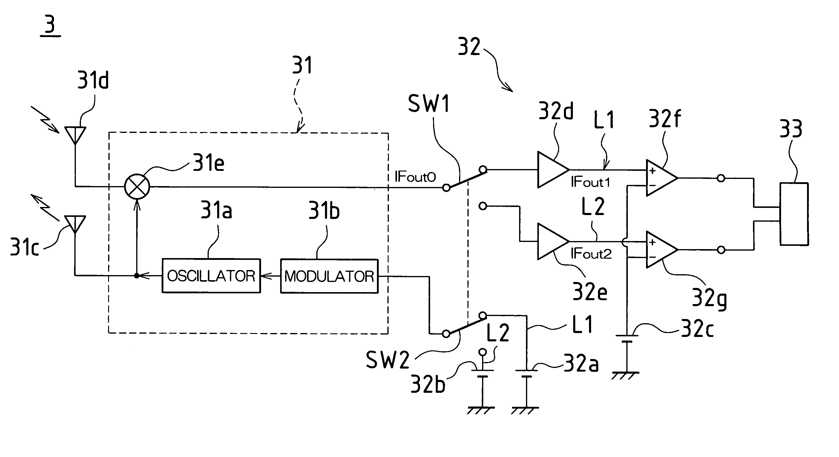
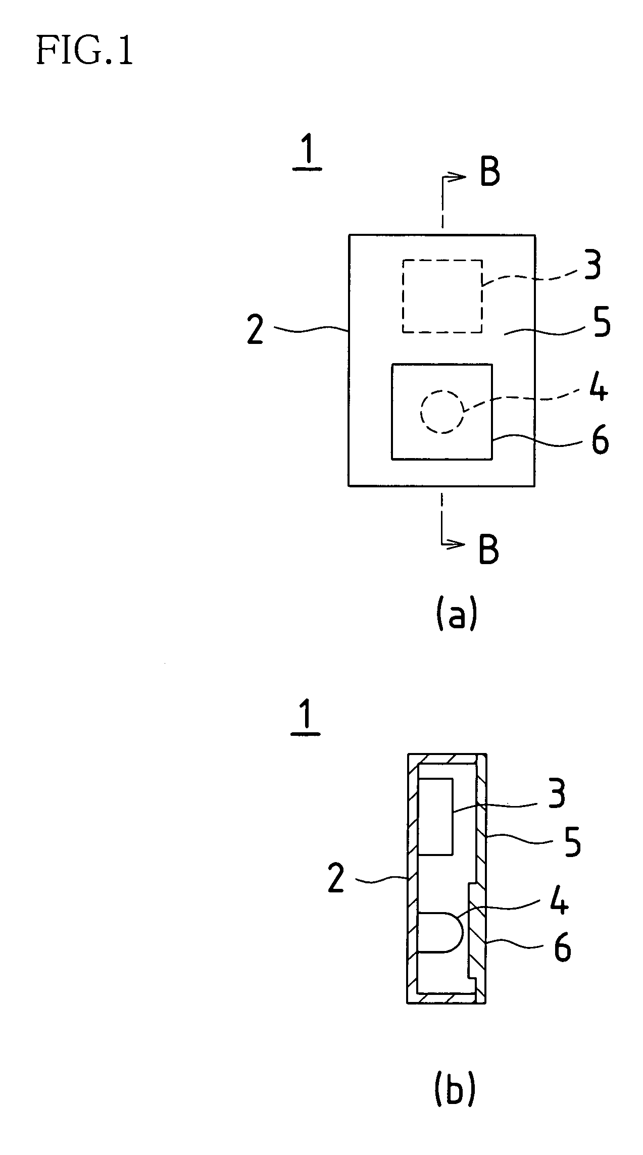
[0031]FIG. 1 show a burglar sensor unit 1 used as a combined sensor in a burglar system according to the present embodiment. FIG. 1(a) illustrates a front view of the burglar sensor unit 1 while FIG. 1(b) a sectional view taken along line B—B of FIG. 1(a). The burglar sensor unit 1 accommodates an MW sensor 3 and a PIR sensor 4 in a case 2, with the front of the case 2 covered with a cover 5 that allows passage of microwaves and a Fresnel lens 6 formed on the front of the IR sensor 4.

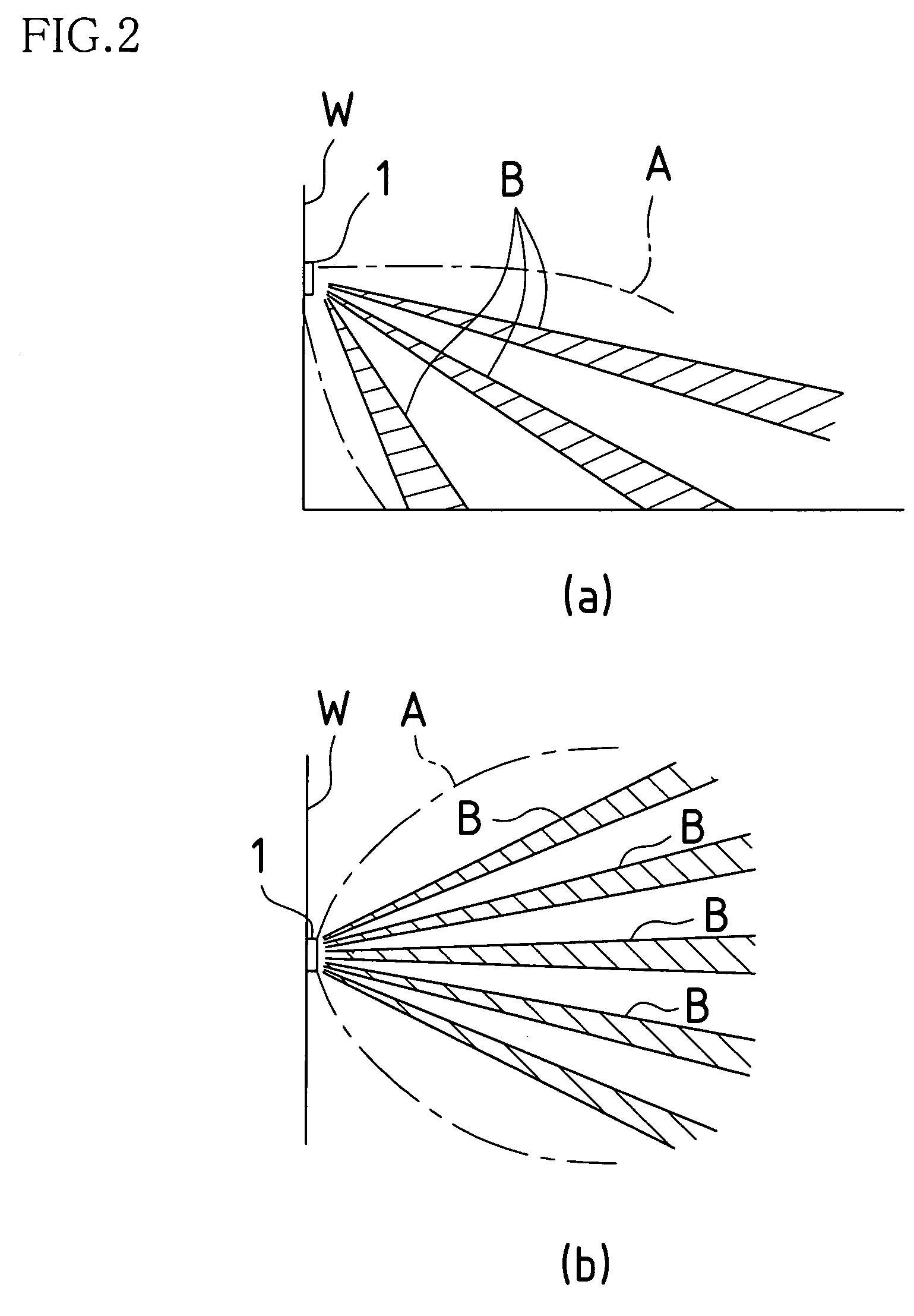
[0032]FIG. 2 show the relationship between unit installation position and detection areas of the MR sensor 3 and the PIR sensor 4 when the burglar sensor unit 1 is installed (installed, for example, on the...


PUM


Abstract

The combined sensor of the present invention is comprised of an MW sensor and a PIR sensor, in which the frequency difference of two microwaves transmitted by the MW sensor is set such that the phase difference between the IF signals received by the MW sensor is approximately 180° when there is an object at the intermediate distance between the maximum detection distance within the target detection area and the maximum detection distance in the event of a deviation of the detection area attributable to mounting error of the infrared sensor 4.

Description

BACKGROUND OF THE INVENTION[0001]1. Technical Field[0002]The present invention relates to a combined sensor provided with a microwave sensor (hereinafter referred to as “MW sensor”)—an active sensor using low-frequency electromagnetic wave rather than visible radiation—and with an infrared sensor (e.g., passive infrared sensor; hereinafter referred to as “PIR sensor”).[0003]2. Prior Art[0004]Combined sensor has been known for use in an intruder detection system (burglar system) as disclosed, for example, by Japanese Unexamined Patent Application Publication No. 11-39574. This type of combined sensor is provided with an MW sensor designed to send microwave toward the detection area, receive the reflected wave from a human body and detect the intruder through Doppler effect and a PIR sensor designed to receive infrared radiation from a human body in the detection area and detect the intruder from the difference between the human body and the ambient temperature. The combined sensor co...

Claims


Application Information

Patent Timeline
Patent Type & Authority Patents(United States)
IPC IPC(8): G08B19/00G01S13/56G01S13/86G08B13/16G08B13/19G08B13/24G08B29/18G08B29/20
CPCG01S13/56G01S13/86G08B29/183G08B13/19G08B13/2494G08B13/1645G08B29/24
Inventor TSUJI, MASATOSHINOGUCHI, MICHINORISEO, CHOLMIN
Owner OPTEX CO LTD
Why Eureka
Try Eureka