Apparatus for correction based upon detecting a camera shaking

a technology of camera and applicator, which is applied in the field of applicator and a method of correction based upon detecting a deviation from the proper position of the camera, can solve the problems of short exposure time of digital video camera, hard to watch the reproduced pictures of the digital video camera, and out of focus of digital still camera

Inactive Publication Date: 2006-01-31
RICOH KK
View PDF34 Cites 122 Cited by
  • Summary
  • Abstract
  • Description
  • Claims
  • Application Information

AI Technical Summary

Benefits of technology

[0014]Accordingly, one object of the present invention is to provide a novel s

Problems solved by technology

As a result, it is hard to watch the reproduced pictures of the digital video camera.
A digital still camera can not realize short exposure time because the sensitivity of the image pickup device is limited.
As a result, the digital still camera goes out of focus when the camera shaking occurs.
That results in the pictures taken by the digital still camera becoming blurry.
That document, ho

Method used


Image

  • Apparatus for correction based upon detecting a camera shaking
  • Apparatus for correction based upon detecting a camera shaking
  • Apparatus for correction based upon detecting a camera shaking

Examples


Embodiment Construction

[0046]A description will now be given of preferred embodiments according to the present invention by referring now to the drawings, wherein like reference numerals designate identical or corresponding structures throughout the views.

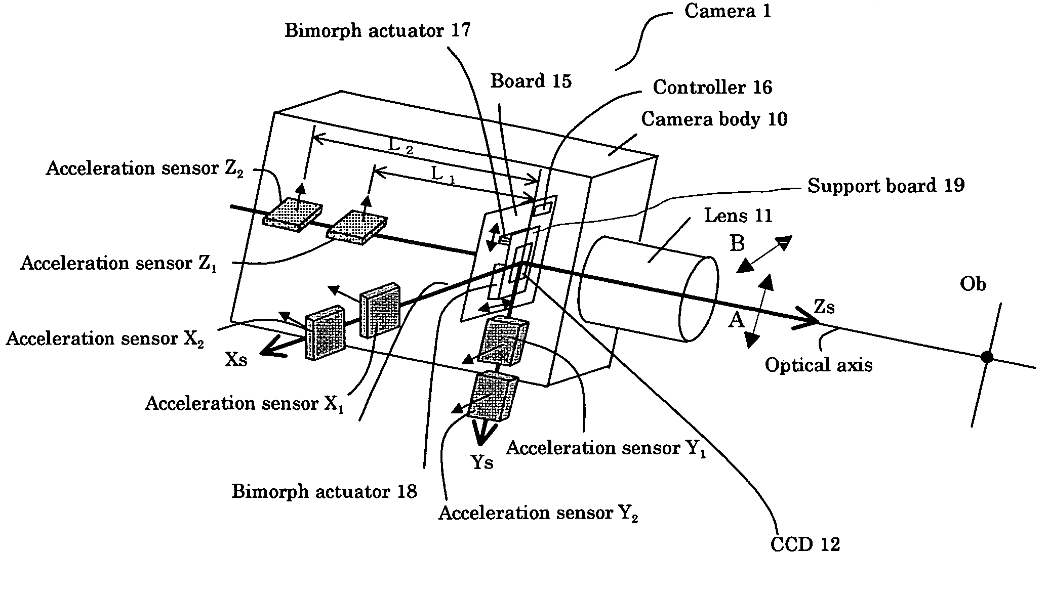
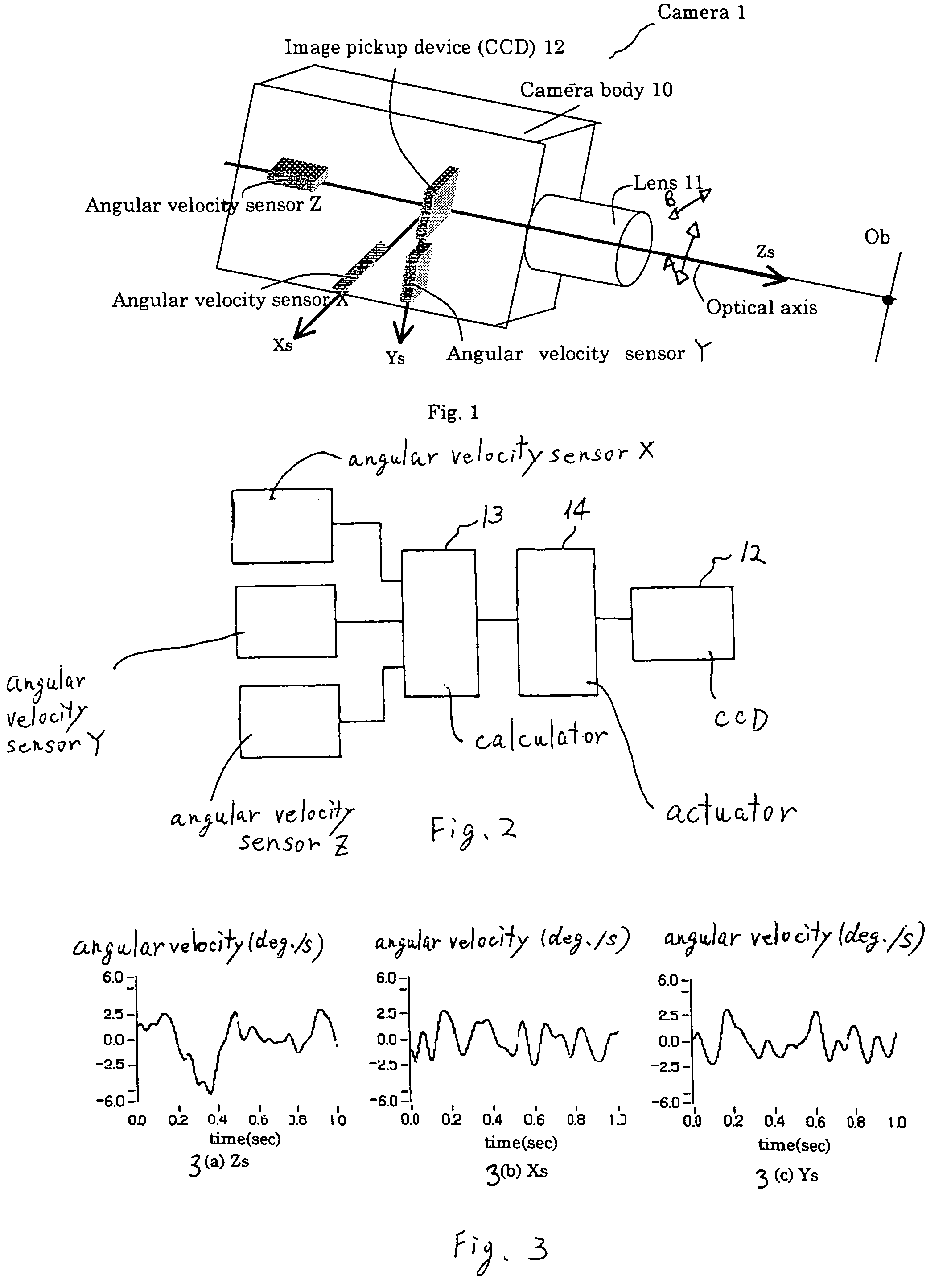
[0047]FIG. 1 shows one preferred embodiment of a camera 1 with a correction mechanism for correcting camera shaking according to the present invention.

[0048]The camera 1 includes a camera body 10 and a lens 11. An angular velocity sensor X, an angular velocity sensor Y, an angular velocity sensor Z, such as piezoelectric gyro sensors, and an image pickup device 12 are set up in the camera body 10. A board (not shown) equipped with a controller and actuators is also set up in the camera body 10. The board equipped with the controller and the actuators is described later. In this embodiment, the image pickup device 12 employs a 2-dimensional CCD.

[0049]The angular velocity sensor Z is located on the optical axis. The camera coordinate system is defined such...


PUM


Abstract

An apparatus for detecting a deviation of a camera as a result of the camera shaking, for example resulting from a hand of the camera operator shaking. The apparatus includes a shaking detector which detects a deviation of the camera from shaking based upon an output of angular velocity sensors which are located on different axes of the camera coordinates. A calculator calculates tilt angles of each of the coordinate axes from outputs of the angular velocity sensors. The rotation regulator rotates an image pickup device around an optical axis of the camera or an axis in parallel with the optical axis.

Description

BACKGROUND OF THE INVENTION[0001]Field of the Invention[0002]The present invention is generally directed to an apparatus and a method for correction based upon detecting a deviation from a proper position of a camera, and more particularly is directed to an apparatus for correcting deviation from the proper camera position caused by shaking, such as hand shaking.BACKGROUND OF THE INVENTION[0003]Digital video cameras and digital still cameras as kinds of cameras are well known. When those kinds of cameras shoot a subject, the optical system of such cameras bring rays of light corresponding to the subject to a focus at an image pickup device and change the light information into electric signals.[0004]When camera shaking occurs in a digital video camera by, e.g., hands of the camera operator shaking, pictures taken by the camera slightly oscillate from the camera shaking. As a result, it is hard to watch the reproduced pictures of the digital video camera.[0005]A digital still camera ...

Claims


Application Information

Patent Timeline
IPC IPC(8): H04N5/228H04N5/232
CPCG03B5/00H04N5/23287H04N5/23258H04N5/23283H04N5/23248G03B2205/0007G03B2217/005H04N23/68H04N23/6812H04N23/686H04N23/687
Inventor SATO, YASUHIROKITAGUCHI, TAKASHI
Owner RICOH KK
Why Eureka
Try Eureka