Method for nonsequentially writing reference spiral servo patterns to a disk to compensate for disk expansion

a reference pattern and spiral servo technology, applied in the field of disk drives, can solve the problems of inability to accurately compensate for disk expansion, high cost of external servo writers, and inability to meet the requirements of clean room environment, so as to facilitate the use of conventional servo algorithms and increase the accuracy of head position errors

Inactive Publication Date: 2006-01-31
WESTERN DIGITAL TECH INC
View PDF3 Cites 124 Cited by
  • Summary
  • Abstract
  • Description
  • Claims
  • Application Information

AI Technical Summary

Benefits of technology

[0011]The reference servo bursts may be substantially contiguous in the radial direction from an outer diameter of the disk to an inner diameter of the disk. Each spiral reference pattern may comprise a plurality of reference servo bursts each having a plurality of high frequency transitions, and the reference servo bursts may be recorded at a periodic interval within each spiral reference pattern. This facilitates the use of a conventional servo algorithm for computing the head position error used for servoing while writing the product servo bursts to the disk.
[0012]A radial length of a product servo burst may define

Problems solved by technology

However, external servo writers are expensive and require a clean room environment so that a head positioning pin can be inserted into the head disk assembly (HDA) without contaminating the disk.
Thus, external servo writers have become an expensive bottleneck in the disk drive manufacturing process.
However, the calibration process will inevitably exhibit some degree of error and the dynamics of the disk drive will change between seeks inducing errors in the radial position of the spiral tracks.
Dynamic errors which degrade the spiral tracks written during an open loop seek include vibration of the HDA, fl

Method used


Image

  • Method for nonsequentially writing reference spiral servo patterns to a disk to compensate for disk expansion
  • Method for nonsequentially writing reference spiral servo patterns to a disk to compensate for disk expansion
  • Method for nonsequentially writing reference spiral servo patterns to a disk to compensate for disk expansion

Examples


Embodiment Construction

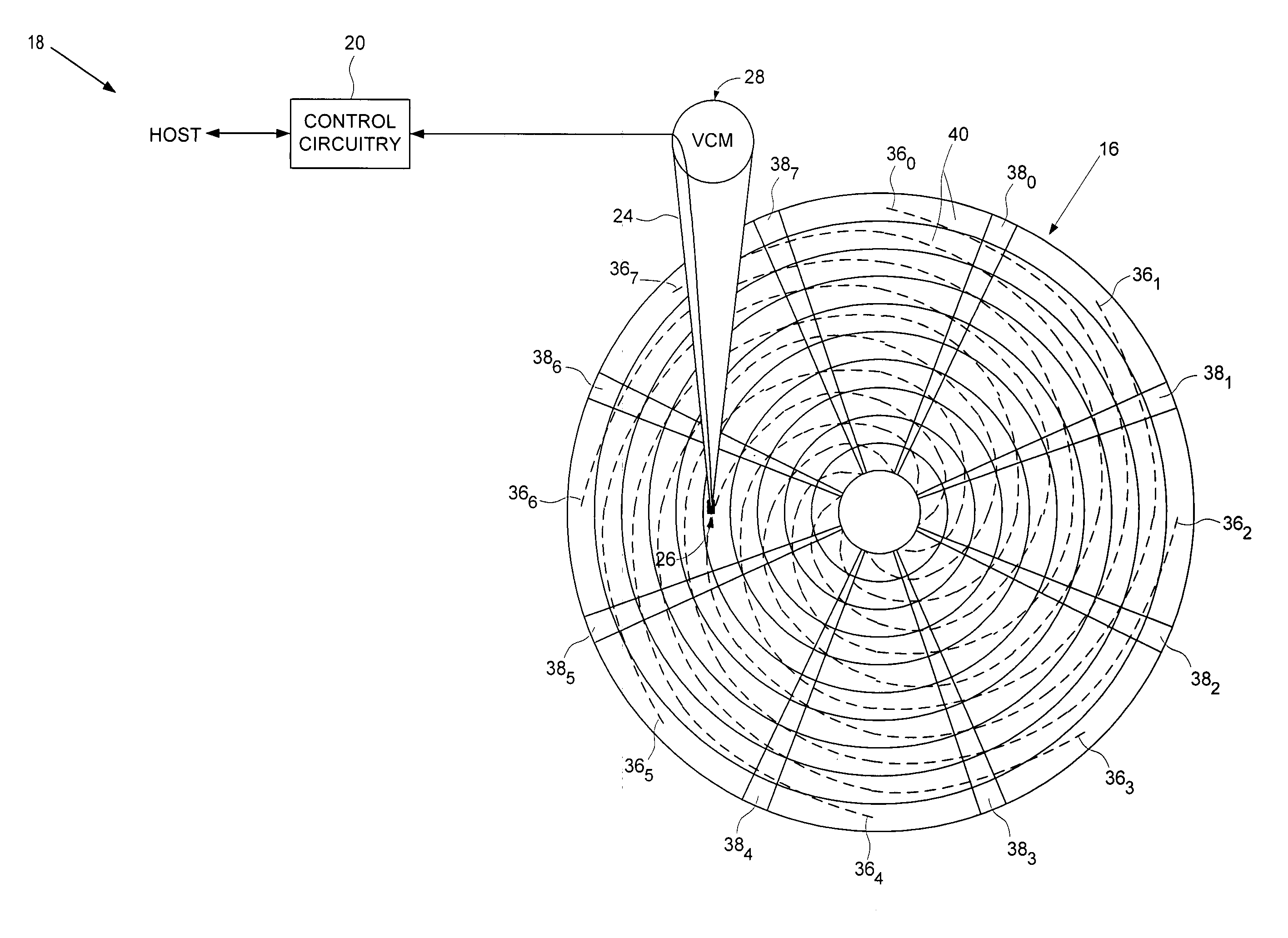
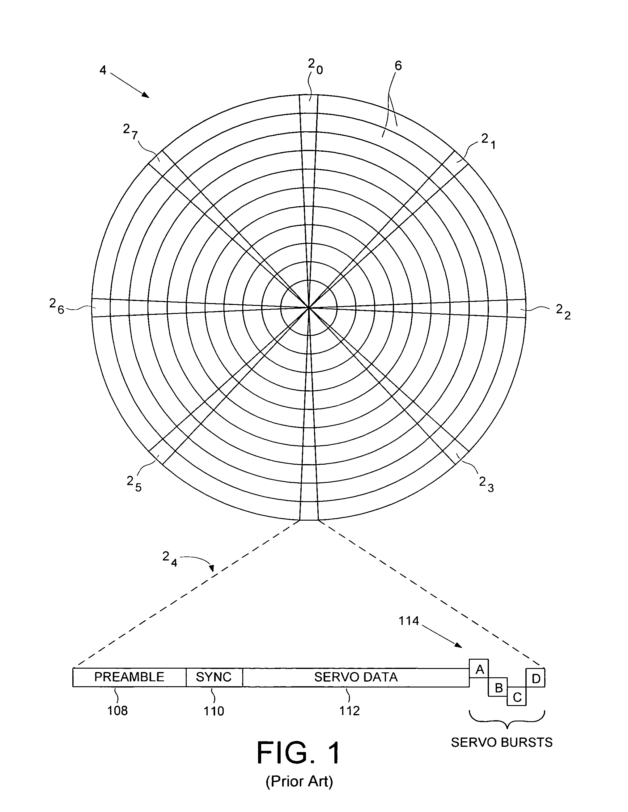
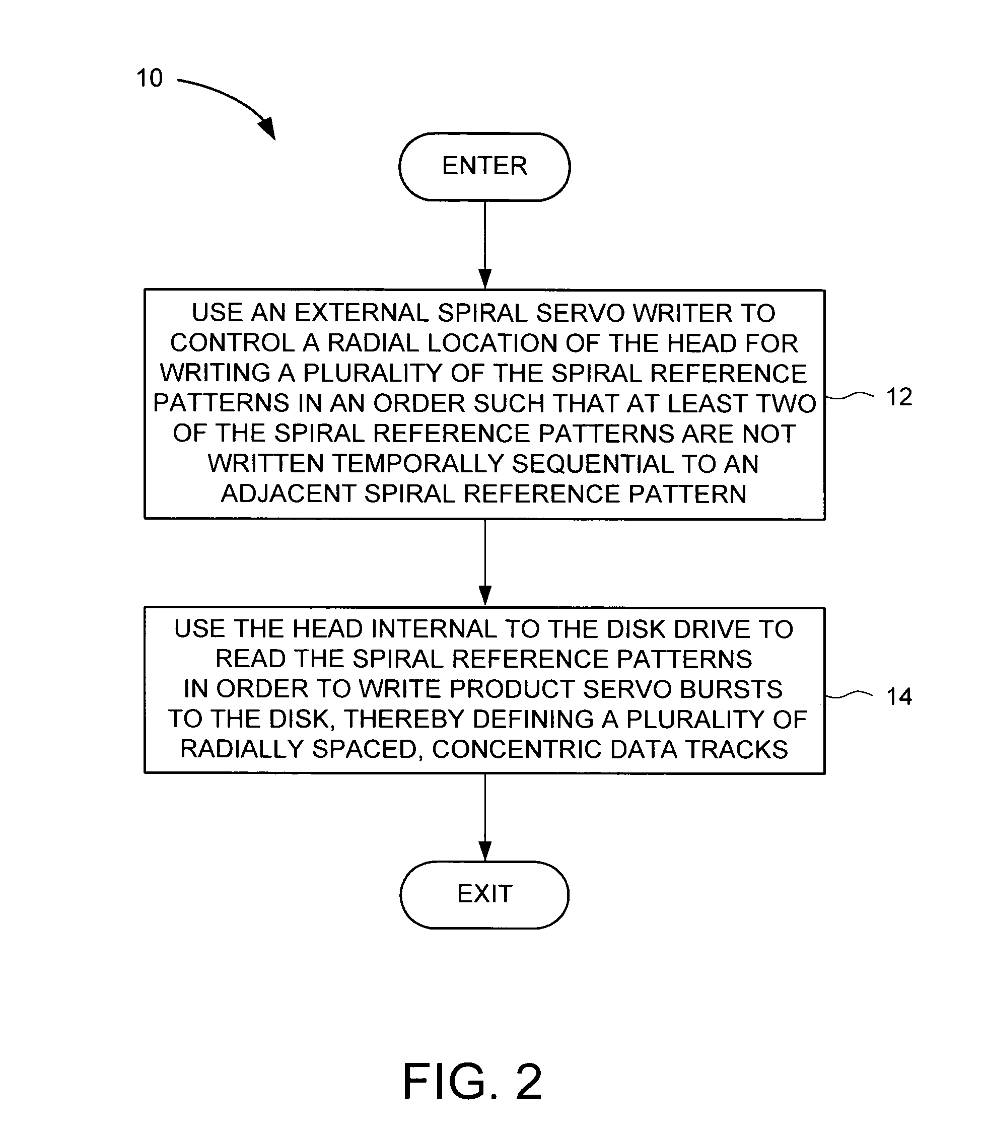
[0021]With reference to FIGS. 1–4, the present invention may be embodied in a method 10 (FIG. 2) for reducing disk thermal expansion effects by nonsequentially writing spiral reference patterns 360–367 (FIG. 3B) to a disk 16 of a disk drive 18 (FIG. 3A). The spiral reference patterns are used for forming product servo bursts 380–387. The disk drive 18 comprises control circuitry 20 and a head disk assembly (HDA) 22 comprising the disk 16, an actuator arm 24, a head 26 connected to a distal end of the actuator arm 24, and a voice coil motor 28 for rotating the actuator arm 24 about a pivot to position the head 26 radially over the disk 16. In the method, an external spiral servo writer 30 is used to control a radial location of the head for writing a plurality of the spiral reference patterns in an order such that at least two of the spiral reference patterns are not written temporally sequential to an adjacent spiral reference pattern (step 12). The head internal to the disk drive i...


PUM


Abstract

A method is disclosed for reducing disk expansion effects while writing spiral reference patterns on a disk. The disk drive comprises control circuitry and a head disk assembly (HDA). In the method, an external spiral servo writer is used to control a radial location of the head for writing a plurality of the spiral reference patterns in an order such that at least two of the spiral reference patterns are not written temporally sequential to an adjacent spiral reference pattern. The head internal to the disk drive is used to read the spiral reference patterns in order to write product servo bursts to the disk, thereby defining a plurality of radially spaced, concentric data tracks.

Description

BACKGROUND OF THE INVENTION[0001]1. Field of the Invention[0002]The present invention relates to disk drives for computer systems. More particularly, the present invention relates to nonsequentially writing spiral reference patterns to compensate for thermal disk expansion during the pattern writing process.[0003]2. Description of the Prior Art and Related Information[0004]When manufacturing a disk drive, servo sectors 20–27 are written to a disk 4 which define a plurality of radially-spaced, concentric data tracks 6 as shown in the prior art disk format of FIG. 1. Each servo sector (e.g., servo sector 24) comprises a preamble 108 for synchronizing gain control and timing recovery, a sync mark 110 for synchronizing to a data field 112 comprising coarse head positioning information such as a track number, and product servo bursts 114 which provide fine head positioning information. During normal operation the product servo bursts 114 are processed by the disk drive in order to mainta...

Claims


Application Information

Patent Timeline
IPC IPC(8): G11B21/02
CPCG11B5/59633
Inventor CLOKE, ROBERT L.
Owner WESTERN DIGITAL TECH INC
Why Eureka
Try Eureka