Power delivery apparatus, systems, and methods

Inactive Publication Date: 2006-01-31
INTEL CORP
View PDF7 Cites 31 Cited by
  • Summary
  • Abstract
  • Description
  • Claims
  • Application Information

AI Technical Summary

Problems solved by technology

However, as the package contact field connection density increases, and the array package pitch decreases, the available power plane connection area may be reduced.
As a result, the amount of power available to the circuit may also be reduced, contributing to power supply droop during peak power consumption periods.
Moreover, vias used as a part of the power path may have a reduced cross-sectional area, increasing resistance and further reducing the power available to the circuit.

Method used


Image

  • Power delivery apparatus, systems, and methods
  • Power delivery apparatus, systems, and methods
  • Power delivery apparatus, systems, and methods

Examples


Embodiment Construction

[0013]In the following detailed description of various embodiments of the invention, reference is made to the accompanying drawings that form a part hereof, and in which are shown by way of illustration, and not of limitation, specific embodiments in which the subject matter may be practiced. In the drawings, like numerals describe substantially similar components throughout the several views. The embodiments illustrated are described in sufficient detail to enable those skilled in the art to practice the teachings disclosed herein. Other embodiments may be utilized and derived therefrom, such that structural and logical substitutions and changes may be made without departing from the scope of this disclosure. The following detailed description, therefore, is not to be taken in a limiting sense, and the scope of various embodiments of the invention is defined only by the appended claims, along with the full range of equivalents to which such claims are entitled.

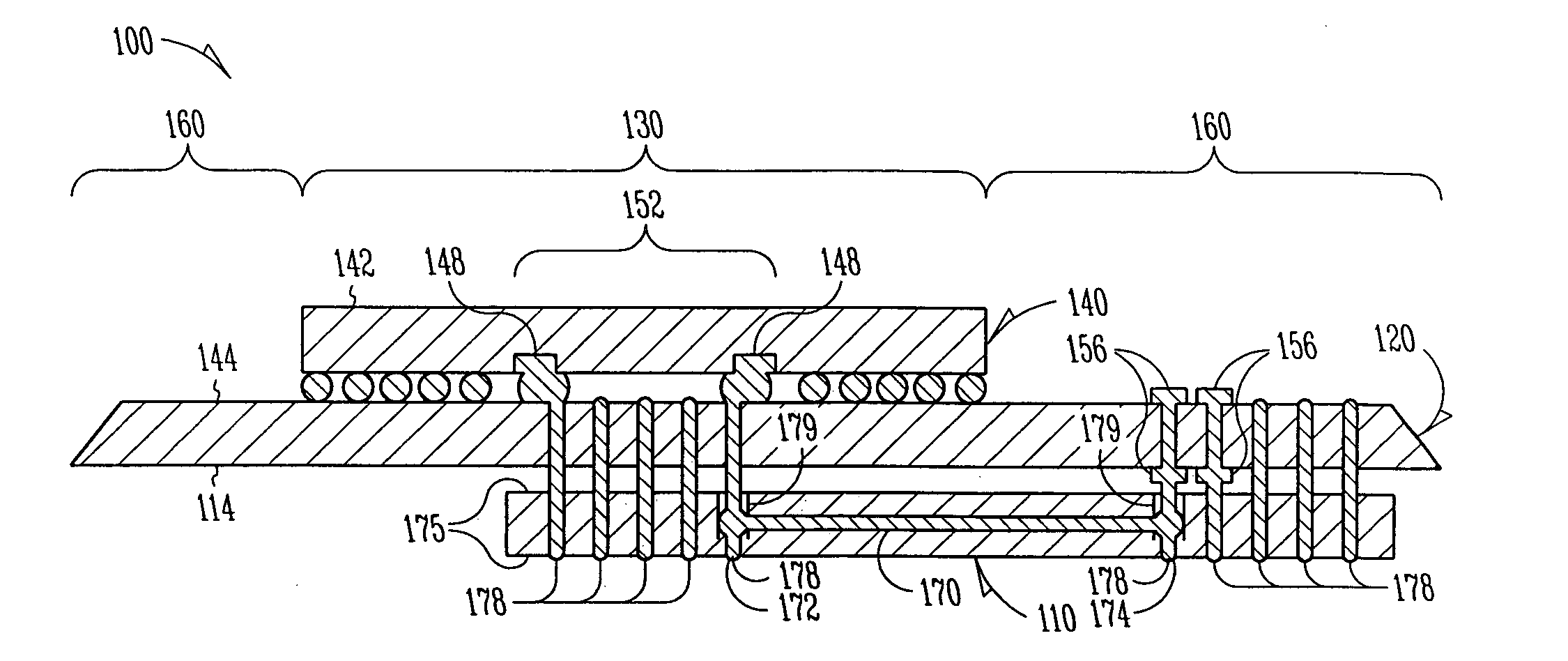
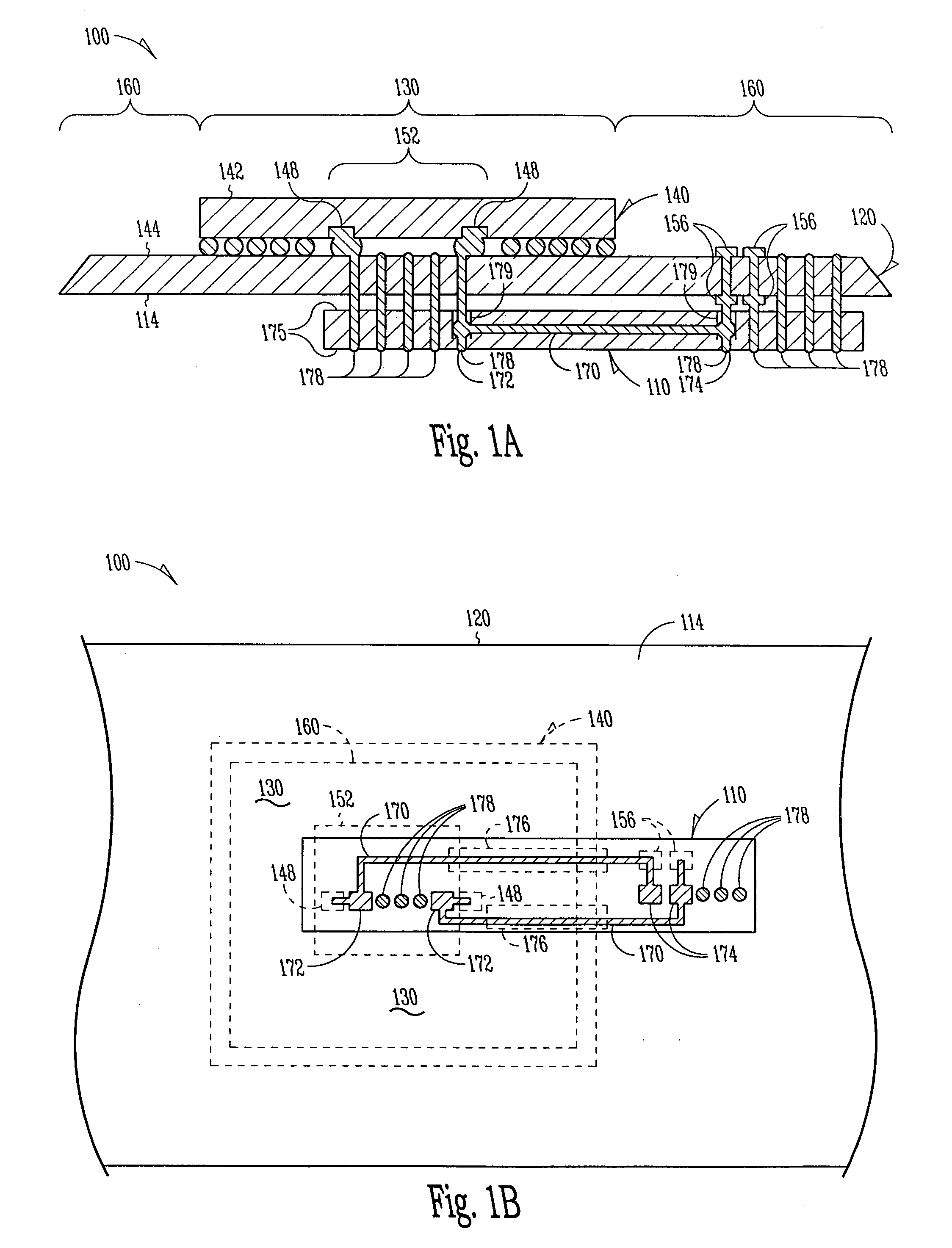
[0014]FIGS. 1A and 1B...


PUM


Abstract

An apparatus and system, as well as fabrication methods therefor, may include a conductor attached to a carrier to bridge a contact field defined by a circuit that can be mounted to a circuit board.

Description

TECHNICAL FIELD[0001]The subject matter disclosed relates generally to apparatus, systems, and methods used to provide electric power to circuitry, including computers and processors.BACKGROUND INFORMATION[0002]Circuits, including processors, may be packaged to include an array of electrical contacts or package pads arranged in the form of a contact field having an inner perimeter and an outer perimeter. In some circuit packages, one or more power contacts are located inside the inner perimeter of the contact field.[0003]When such packages are mounted to a circuit board, vias may be used as part of the electrical path from one or more circuit board power planes to the power contacts. However, as the package contact field connection density increases, and the array package pitch decreases, the available power plane connection area may be reduced. This reduction can be caused by the presence of antipads (i.e., clearance holes) introduced into the circuit board to accommodate various c...

Claims


Application Information

Patent Timeline
IPC IPC(8): H05K7/06H05K1/02H05K1/14H05K3/22H05K3/34
CPCH05K1/141H05K3/222H05K1/0263H05K3/3447H01L2924/15192H05K2201/10545H05K2201/10734H01L2224/73253H05K2201/10303H05K1/144H05K3/36H05K1/14
Inventor ALGER, WILLIAMLONG, GARYBRIST, GARYMEJIA, CARLOS
Owner INTEL CORP
Why Eureka
Try Eureka