Table saw with improved safety system

a table saw and safety system technology, applied in band saws, metal sawing accessories, manufacturing tools, etc., can solve the problems of table saws presenting perhaps the greatest risk of injury, table saws presenting a risk of injury to users

Inactive Publication Date: 2006-02-07
SAWSTOP HLDG LLC
View PDF358 Cites 162 Cited by
  • Summary
  • Abstract
  • Description
  • Claims
  • Application Information

AI Technical Summary

Problems solved by technology

Of all the tools in a woodworking shop, table saws present perhaps the greatest risk of injury.
Table saws present a risk of injury to users because the spinning blade is often exposed when in use.

Method used


Image

  • Table saw with improved safety system
  • Table saw with improved safety system
  • Table saw with improved safety system

Examples


Embodiment Construction

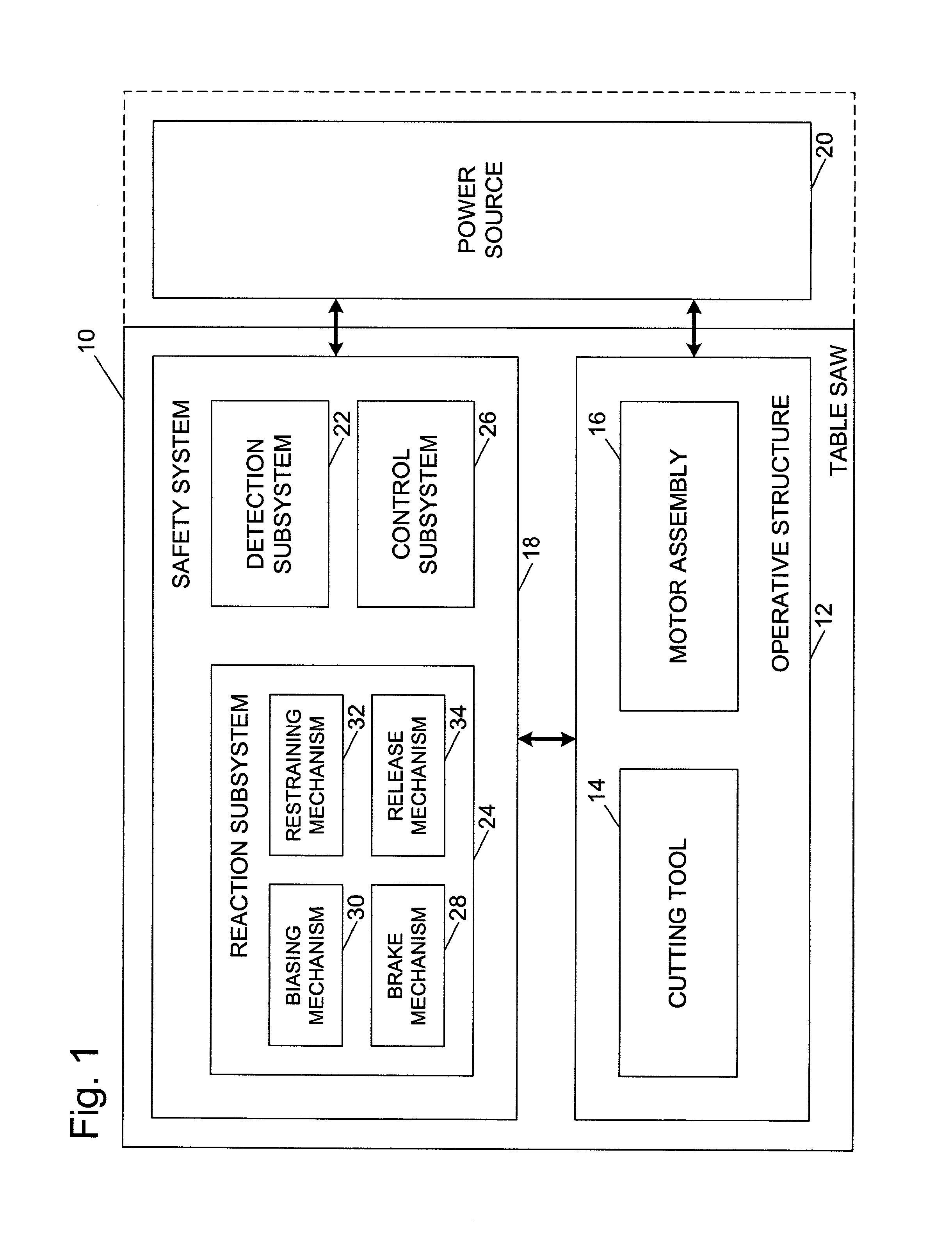
[0025]A table saw according to the present invention is shown schematically in FIG. 1 and indicated generally at 10. Table saw 10 may be any of a variety of different types and configurations of table saw adapted for cutting workpieces, such as wood, plastic, etc. Table saw 10 includes an operative structure 12 having a cutting tool 14 and a motor assembly 16 adapted to drive the cutting tool. Table saw 10 also includes a safety system 18 configured to minimize the potential of a serious injury to a person using table saw 10. Safety system 18 is adapted to detect the occurrence of one or more dangerous, or triggering, conditions during use of table saw 10. If such a dangerous condition is detected, safety system 18 is adapted to engage operative structure 12 to limit any injury to the user caused by the dangerous condition.

[0026]Table saw 10 also includes a suitable power source 20 configured to provide power to operative structure 12 and safety system 18. Power source 20 may be an ...


PUM

PropertyMeasurementUnit
perimeteraaaaaaaaaa
rotationaaaaaaaaaa
heightaaaaaaaaaa

Abstract

A table saw having a brake mechanism configured to engage and stop a blade is disclosed. The table saw includes a brake positioning system configured to adjust the position of the brake mechanism to maintain the brake mechanism in an operative position relative to the blade as the blade is raised and lowered.

Description

CROSS-REFERENCE TO RELATED APPLICATIONS[0001]This application is a continuation-in-part of the following U.S. patent applications, all of which are hereby incorporated by reference: Ser. No. 09 / 676,190, filed Sep. 29, 2000, Ser. No. 09 / 929,221, filed Aug. 13, 2001, Ser. No. 09 / 929,226, filed Aug. 13, 2001 now U.S. Pat. No. 6,920,814, Ser. No. 09 / 929,227, filed Aug. 13, 2001, Ser. No. 09 / 929,234, filed Aug. 13, 2001, Ser. No. 09 / 929,235, filed Aug. 13, 2001, Ser. No. 09 / 929,236 now abandoned, filed Aug. 13, 2001, Ser. No. 09 / 929,237, filed Aug. 13, 2001, Ser. No. 09 / 929,238, filed Aug. 13, 2001, Ser. No. 09 / 929,240, filed Aug. 13, 2001, Ser. No. 09 / 929,241, filed Aug. 13, 2001, Ser. No. 09 / 929,242, filed Aug. 13, 2001, Ser. No. 09 / 929,244 now U.S. Pat. No. 6,857,345 filed Aug. 13, 2001, Ser. No. 09 / 929,425, filed Aug. 13, 2001, and Ser. No. 09 / 929,426, filed Aug. 13, 2001.[0002]This application claims the benefit of and priority from the following U.S. Provisional Patent Applications...

Claims


Application Information

Patent Timeline
Patent Type & Authority Patents(United States)
IPC IPC(8): B26D1/18B27B3/28B23D45/06B23D47/08B23D55/08B23D59/00B27B5/38B27B13/14B27G19/00B27G19/02F16P3/12F16P3/14
CPCB23D45/06B23D45/067B23D47/08B23D55/08B23D59/001F16P3/148B27B13/14B27G19/00B27G19/02F16P3/12F16P3/14B27B5/38Y10T83/089Y10T83/7726Y10T83/773
Inventor GASS, STEPHEN F.FANNING, DAVID A.
Owner SAWSTOP HLDG LLC
Why Eureka
Try Eureka