Gingival tissue retractor

a tissue retractor and gingival technology, applied in the field of tissue retractors, can solve the problems of insufficient wideness of instruments wide enough to adequately retract larger segments of tissue from the central groove, insufficient wideness to adequately retract remaining obstructing tissues, and difficult banding of molars and premolars, etc., to achieve the effect of convenient cleaning, convenient manufacturing, and convenient cleaning

Inactive Publication Date: 2006-02-07
PERRET JR GERARD A
View PDF11 Cites 27 Cited by
  • Summary
  • Abstract
  • Description
  • Claims
  • Application Information

AI Technical Summary

Benefits of technology

[0018]For versatility in use, both apices of the oval or diamond working end can be arranged with a first and second portion as described above. In addition, the oval or diamond working end is preferably concave to assist in conforming to the exterior surface of a tooth. If desired, the working end of the tool can be angled with respect to the axis of the shaft, and the shaft or handle can be formed with an angle to improve the comfort of a patient when the tool is used on posterior teeth and to permit the professional using the tool to position the tool in the proper location. With this arrangement, the tool of the present invention is suitable for either a right handed or left handed professional, or for use on either the right or left side of a patient's mouth, or on upper or lower teeth.
[0019]Although the tool of the present invention can be made of a metal material to be durable and easy to clean, in order to make the tool inexpensive and easy to manufacture, the tool is preferably molded as a single piece of a plastic material. The material can be either a high quality, heat resistant, sterilizable plastic so that the tool can be sterilized and reused, or it can be a less expensive non-sterilizable plastic so that it will be inexpensive enough to be discarded after a single use. In either case, the material is pref

Problems solved by technology

Due to their anatomy, molars and premolars, collectively known as the posterior teeth, often pose a particularly difficult banding problem.
But when both the central groove and any other area are obstructed, a dilemma arises.
Those instruments narrow enough to retract tissue from the central groove are insufficiently wide to adequately retract the remaining obstructing tissues.
Those instruments wide enough to adequately retract larger segments of tissue cannot fit into the central groove to adequately retract this tissue.
Such attempts, in fact, might actually crush or lacerate this thin piece of gingival tissue as the wider portions of tissue are retracted.
In addition, even if tissue retraction were adequate, the clamp portion of this de

Method used


Image

  • Gingival tissue retractor
  • Gingival tissue retractor
  • Gingival tissue retractor

Examples


Embodiment Construction

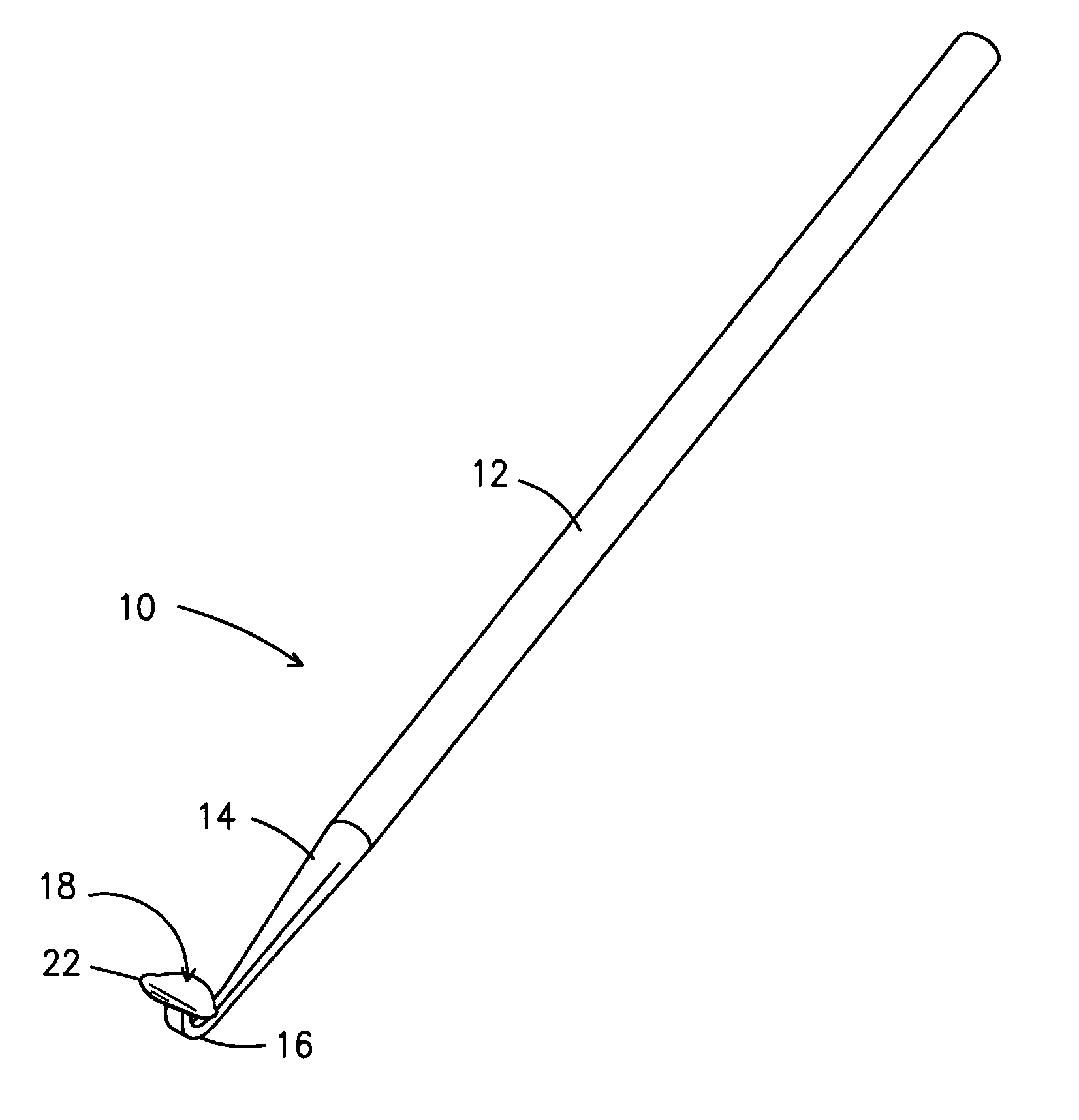
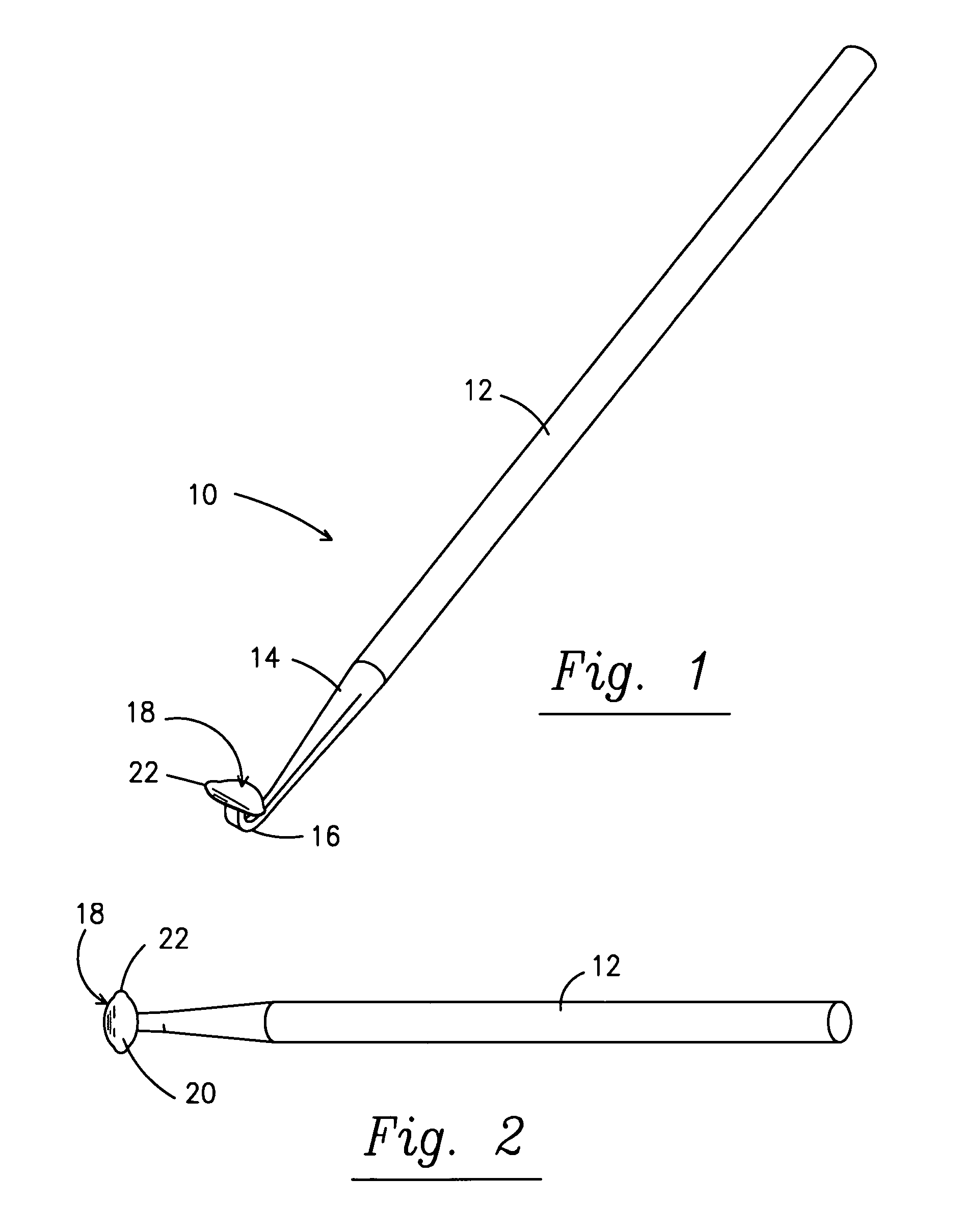
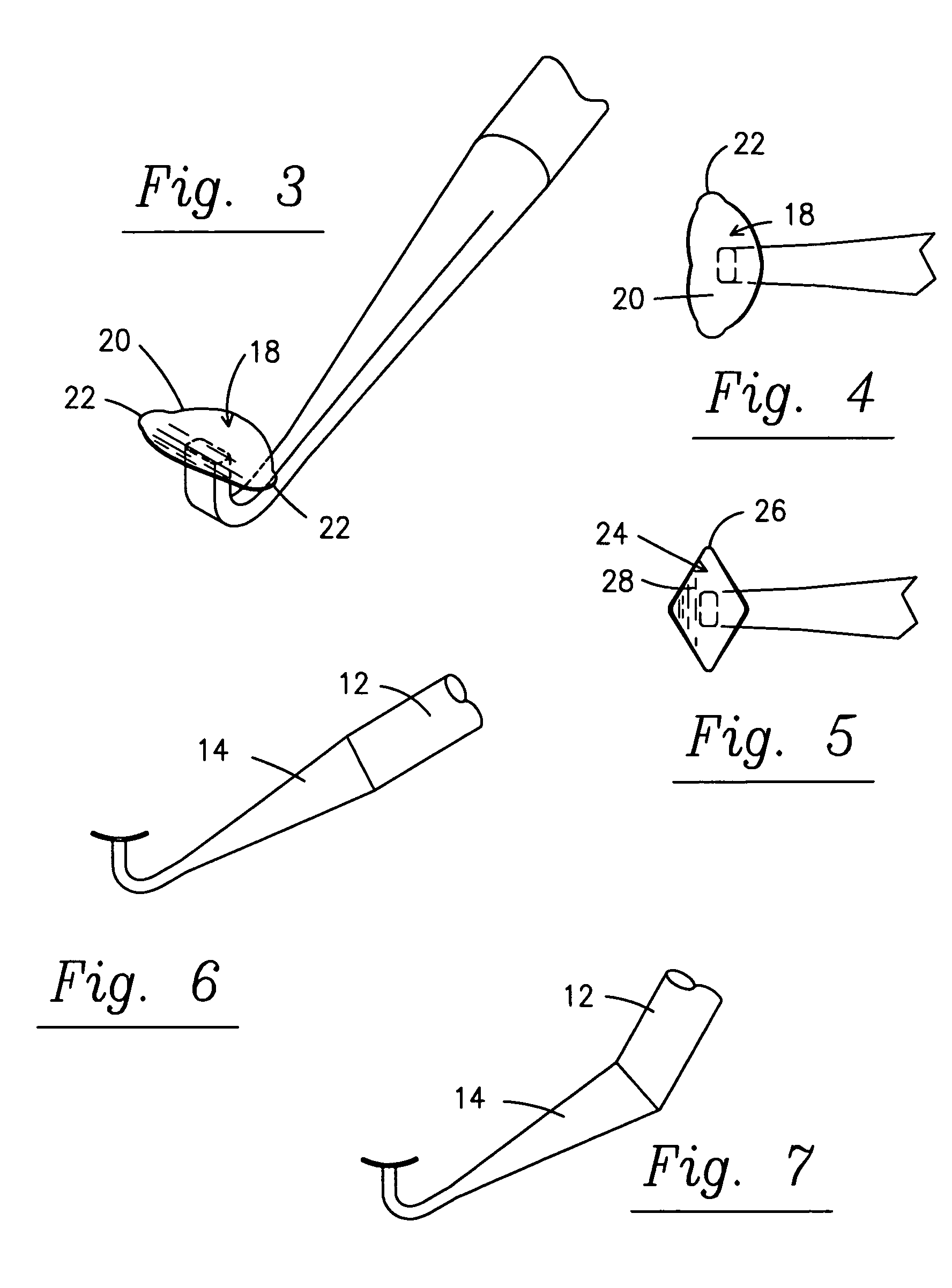
[0031]A gingival tissue retraction tool is shown generally at 10 in FIG. 1 and is comprised of an elongated shaft 12 having a secondary end portion 14 terminating in a J-shaped curve 16 for supporting a working end 18. As can best be seen in FIG. 2, in the preferred embodiment of the invention, the working end 18 is generally curved, preferably oval in shape, with the long axis of the oval working end arranged generally perpendicular to the axis of the shaft 12. Additionally, if desired, the working end 18 of FIG. 1 can be angled with respect to the axis of the shaft. With this orientation, the apices 20 of the oval working end extend laterally from the shaft to provide working surfaces, as will be described later.

[0032]In the enlarged view of FIG. 3 it will be noted that each apex 20 of the oval working end 18 is provided with a small projection 22 that is convex and forms a leading edge working surface that is much narrower than the apex 20 of the working end 18. Thus, the apex 20...


PUM


Abstract

A dental tool for retracting gingival tissue is provided that includes a shaft and a working end member, the working end member having an operative end including a first portion sufficiently narrow to retract tissue from a groove of a tooth and a second portion, adjacent the first portion, and being sufficiently wide to retract tissue from an area of the tooth adjacent the groove. A method for retracting gingival tissue is also disclosed.

Description

FIELD OF THE INVENTION[0001]The present invention concerns a tissue retractor and, in particular, a gingival tissue retractor and, more specifically, a gingival tissue retractor which is particularly suited for retracting gingival tissue as an aid in fitting orthodontic appliances, and a method for retracting such tissues.BACKGROUND OF THE INVENTION[0002]During the course of orthodontic treatment, small appliances and attachments, commonly known as “braces”, are affixed to the teeth of the patient. While there are various types of such appliances and attachments available for use in orthodontic treatment, for the purposes of the current invention and its application, our discussion is limited to an attachment method or “brace” known in the trade as a band. A band is a one-piece ring, made of a thin metal alloy, to which various orthodontic attachments can be welded or soldered. An orthodontic band is designed to fit around the circumference of a tooth in much the same manner as a ri...

Claims


Application Information

Patent Timeline
IPC IPC(8): A61C3/00A61C7/02A61C9/00
CPCA61C3/00A61C7/02A61C9/0033
Inventor PERRET, JR., GERARD A.
Owner PERRET JR GERARD A
Why Eureka
Try Eureka