Check patentability & draft patents in minutes with Patsnap Eureka AI!

Robot with tactile sensor device

Inactive Publication Date: 2006-02-07
FSI INTERNATIONAL INC
View PDF28 Cites 74 Cited by
  • Summary
  • Abstract
  • Description
  • Claims
  • Application Information

AI Technical Summary

Benefits of technology

[0015]The use of a tactile sensor device such as one including a touch sensitive surface or the like for robot teaching and calibration procedures can advantageously simplify many aspects of these procedures. For example, certain touch sensitive surfaces can output a signal indicative of precise positional information within a coordinate system such as an X-Y coordinate system because of a high-resolution capability. Also, certain touch sensitive surfaces can provide information related to touch force that can be used to enhance the accuracy and repeatability of sensing. Thus, tactile sensor devices such as touch sensitive surfaces or touch screens can provide highly accurate positional information for the benefit of a robot.

Problems solved by technology

Generally, however, such information may not be accurate enough to assure that the robot can operate properly without damaging any systems component or the objects being handled.
Additionally, whenever the system is serviced or a machine component wears, settles, or malfunctions and requires replacement, upgrade, or service, the robot must be re-taught positions relative to the modified component(s) because the robot cannot automatically adapt to such variations.
If the robot is not re-taught properly within close tolerances, serious damage to the robot or loss of expensive objects such as wafers or objects can result.
Besides consuming many hours, manual teaching procedures can introduce subjectivity, and thus a significant possibility for errors.
This creates a problem of reproducibility.
In particular, both approaches can be difficult to utilize with robots having more than three degrees of movement as more degrees of motion generally require more numerous and complex sensing movements.
Increased complexity of the sensing approach can be expensive and can introduce difficulties in calibration and teaching especially where precise sensing is not possible.
Moreover, motor torque sensing is generally limited to single axis motion such as planar motion for teaching of slots of a cassette.
Thus, this type of sensing cannot handle non-planar motion such as is required for accommodating multiple entry angles for certain cassettes or the like.

Method used


Image

  • Robot with tactile sensor device
  • Robot with tactile sensor device
  • Robot with tactile sensor device

Examples


Embodiment Construction

[0031]The embodiments of the present invention described below are not intended to be exhaustive or to limit the invention to the particular embodiments disclosed in the following detailed description. Rather, the embodiments are described so that others, particularly those skilled in the art, can understand the principles and practices of the present invention.

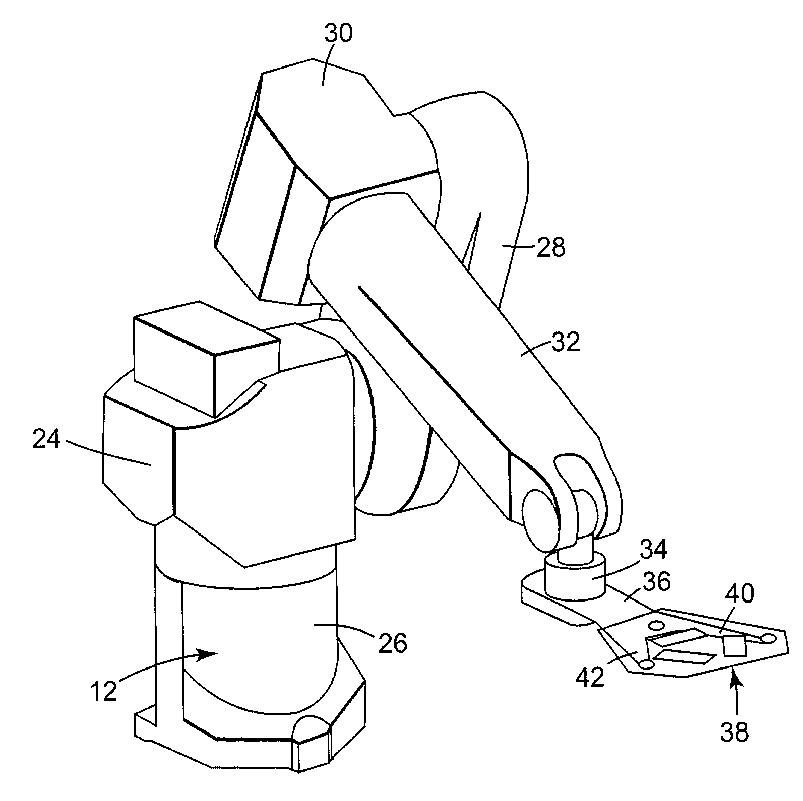
[0032]The terms “tactile sensor device,”“touch screen,”“touch pad,” or “touch panel” as used herein, generally refer to a device having a touch sensitive surface that can detect contact with another tangible structure, object, entity, or the like. In particular, a touch sensitive surface can indicate not only that the surface is touched but also can provide positional information about where the surface is touched such as information with respect to a frame of reference or coordinate system or the like of the touch sensitive surface. Such positional information can advantageously be used to determine the position of a robot w...


PUM

PropertyMeasurementUnit
Sensitivityaaaaaaaaaa

Abstract

Methods and apparatuses for calibrating and teaching a robot to accurately work within a work environment. The present invention preferably provides one or more tactile sensor devices that may be operatively coupled with a robot or positioned at one or more desired locations within a work environment of the robot. In one aspect of the present invention a method comprises the steps of providing a touch sensitive surface in the work environment, causing the touch sensitive surface to contact an object, generating a signal indicative of the position of the contact with respect to the touch sensitive surface, and using information comprising the generated signal to teach the robot the location of the contact in the work environment.

Description

[0001]This application claims the benefit of U.S. Provisional Application Ser. No. 60 / 419,991, filed Oct. 21, 2002, entitled “ROBOT WITH TACTILE SENSOR DEVICE,” which application is incorporated herein by reference in its entirety.FIELD OF THE INVENTION[0002]The present invention relates to robotic handling systems. In particular, the present invention is directed to apparatuses and methods for transferring objects between various locations within a work environment wherein a tactile sensor is used to calibrate positional relationships.BACKGROUND OF THE INVENTION[0003]In fabricating typical microelectronic devices, certain objects are often transferred between various locations within a work environment by robotic handling systems. These objects frequently include substrates or wafers for forming microelectronic devices. They may be substrates including partially or fully completed microelectronic devices, cassettes or other carriers, or other objects needed to be moved between diff...

Claims


Application Information

Patent Timeline
IPC IPC(8): G05B15/00G05B19/00B25J9/16B25J13/08G05B19/423G06F19/00
CPCB25J9/1692G05B19/425G05B2219/45063G05B2219/40625B25J9/16B25J13/08
Inventor CORDELL, ANDREW W.REDDING, KEITH W.
Owner FSI INTERNATIONAL INC
Features
  • R&D
  • Intellectual Property
  • Life Sciences
  • Materials
  • Tech Scout
  • Unparalleled Data Quality
  • Higher Quality Content
  • 60% Fewer Hallucinations
Learn More