Valve suitable for use in an oil circuit of an internal combustion engine

a technology of oil circuit and valve, which is applied in the direction of auxilary lubrication, separation process, instruments, etc., can solve the problems of large space available, risk of screen deformation,

Active Publication Date: 2006-02-14
MANN HUMMEL GMBH
View PDF8 Cites 22 Cited by
  • Summary
  • Abstract
  • Description
  • Claims
  • Application Information

AI Technical Summary

Benefits of technology

[0003]It is an object of the present invention to provide an improved valve for a filter element which avoids the disadvantages described above.

Problems solved by technology

The disadvantage of such an element is that a relatively large amount of space must be available in order for the quantity of oil passing through the screen not to suffer an excessive pressure drop.
Furthermore, there is a risk of the screen being deformed due to the high pressure of the oil, especially when the screen surface is soiled.

Method used


Image

  • Valve suitable for use in an oil circuit of an internal combustion engine
  • Valve suitable for use in an oil circuit of an internal combustion engine
  • Valve suitable for use in an oil circuit of an internal combustion engine

Examples


Embodiment Construction

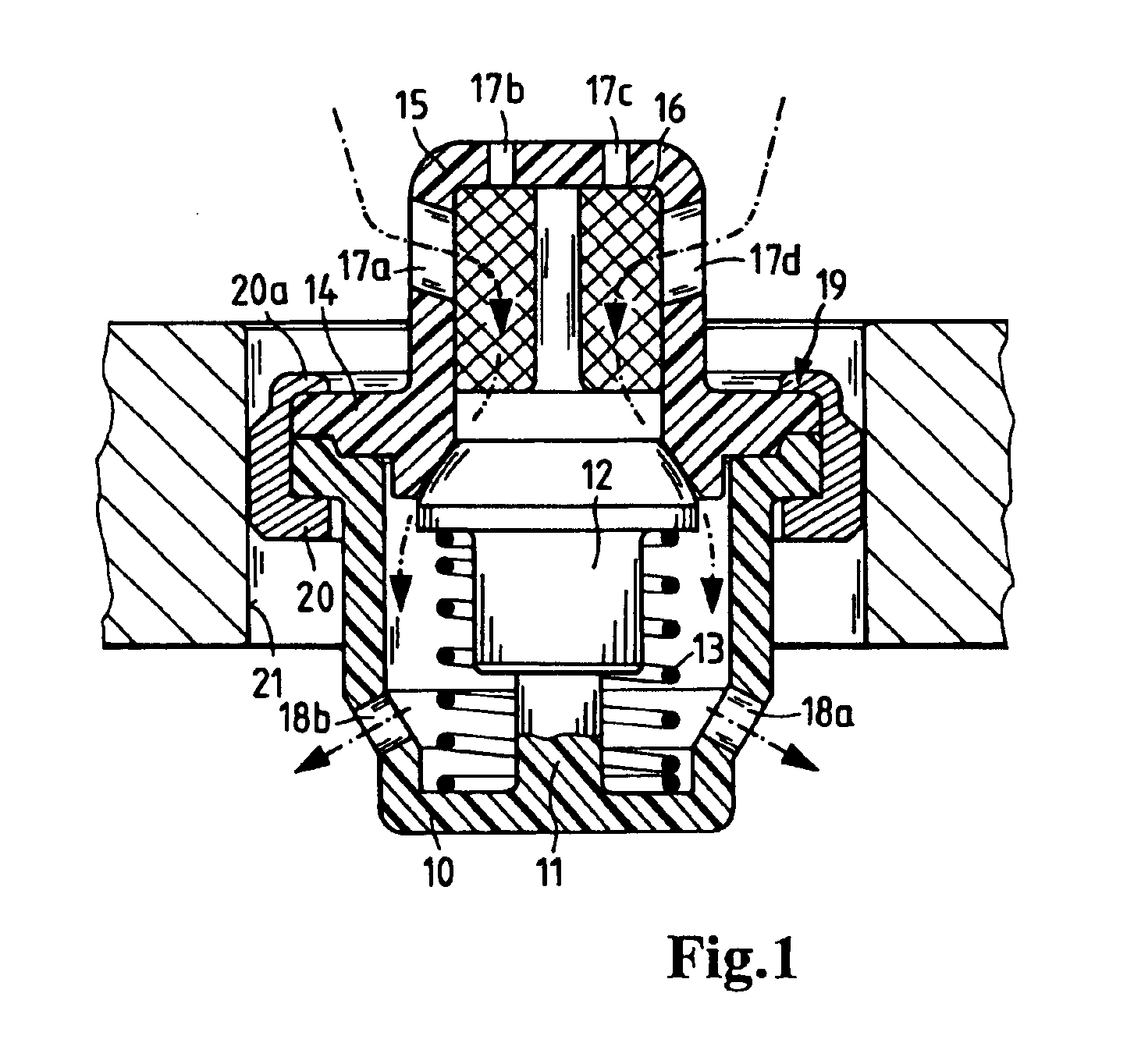
[0020]The valve according to FIG. 1 comprises a supporting dome 10, which is equipped with a guide pin 11. A valve body 12 engages over the guide pin 11 and is pushed by a compression spring 13 against the valve seat of a valve disk 14. The valve disk 14 is provided with a hood 15 in its central area. Within this hood 15 is a screen element 16. The valve disk 14 with the hood 15 and the screen element 16 are all made of synthetic resin material. This makes it readily possible to embed the screen element 16 in the hood 15 during its manufacture. For example, the screen element 16 may be embedded in the plastic of the hood 15 by extrusion. The oil flows through the screen element, which retains particles of dirt as the oil flows through.

[0021]In another variant, the hood 15 has openings 17a, 17b, 17c, 17d which serve to allow admission of the oil flowing through the valve. For example, the valve has an opening pressure in the range of 0.1 to 0.4 bar. The inflowing oil opens the valve,...


PUM

PropertyMeasurementUnit
opening pressureaaaaaaaaaa
pressureaaaaaaaaaa
liquid throughputaaaaaaaaaa

Abstract

A valve, in particular for the oil circuit of an internal combustion engine. The valve includes a supporting dome, a valve body situated therein, a valve disk which is connected to the supporting dome and has an opening which can be closed by the valve body, and an element having a spring action which urges the valve body into the position in which the valve body closes the opening of the valve disk; the valve disk including a receptacle for a screen element, and the screen element being permanently connected to the valve disk.

Description

BACKGROUND OF THE INVENTION[0001]This invention relates to a valve, in particular for the oil circuit of an internal combustion engine.[0002]A valve of this general type disposed in a liquid filter is already known from German Utility Model No. DE 200 06 974 U1. The disclosed liquid filter has a replaceable filter insert and a supporting dome which supports the filter insert. A filter bypass valve is arranged in the supporting dome, where a valve body of the filter bypass valve cooperates with a sealing surface formed by an end disk of the filter insert. The valve body closes an opening, which is essentially in a stationary arrangement during filter operation, but can be removed from the valve body. A screen provided on the valve insert is connected upstream from the opening in the sealing surface. The screen functions to capture particles of dirt during the open states of the filter bypass valve. The screen comprises, for example, a pot-shaped or hood-shaped element or a screen dis...

Claims


Application Information

Patent Timeline
Patent Type & Authority Patents(United States)
IPC IPC(8): E03B3/18B01D29/11B01D35/147F01M13/00F16K15/02
CPCB01D29/114B01D35/147F01M13/0011F16K15/026B01D29/21B01D29/54B01D35/153B01D35/16B01D2201/305F01M2001/1064Y10T137/7935Y10T137/2605Y10T137/8085
Inventor MACK, KLAUS
Owner MANN HUMMEL GMBH
Why Eureka
Try Eureka