Valve with high temperature rating

a valve and high temperature technology, applied in the field of valves, can solve problems such as affecting the quality of thin film

Active Publication Date: 2009-08-11
ASM IP HLDG BV
View PDF17 Cites 0 Cited by
  • Summary
  • Abstract
  • Description
  • Claims
  • Application Information

AI Technical Summary

Benefits of technology

[0010]It is a principle object and advantage of the present invention to provide an improved valve for regulating fluids at high temperatures, particularly for use in semiconductor processing equipment.
[0011]In one aspect, the invention provides a valve comprising a valve seat and a movable diaphragm. The valve seat defines a fluid orifice and is formed at least partially of polybenzimidazole. The diaphragm is sized and configured to bear against the fluid orifice to substantially block fluid flow through the orifice.
[0012]In another aspect, the invention provides a valve seat comprising a seat body defining a fluid orifice, the seat body being formed at least partially of polybenzimidazole.
[0013]In yet another aspect, the invention provides a semiconductor processing system comprising a substrate processing chamber, a gas delivery system for delivering process gases to the processing chamber, and at least one valve configured to regulate flow of the process gases from the gas delivery system. The valve comprises a valve seat and a movable diaphragm. The valve seat defines a fluid orifice and is at least partially formed of polybenzimidazole. The diaphragm is sized and configured to bear against the fluid orifice to substantially block fluid flow through the orifice.
[0014]In yet another aspect, the invention provides a valve at least partially formed of polybenzimidazole.
[0015]In still another aspect, the invention provides a method of delivering a process gas to a substrate reaction chamber. The method comprises providing a substrate reaction chamber, providing a valve at least partially formed of polybenzimidazole, and delivering a process gas through the valve to the reaction chamber.

Problems solved by technology

Condensation of the precursors, in particular in the conduits between the precursor sources and the reaction chamber as well as on the substrate, will seriously impair the quality of the thin film.
Therefore, an ALD process is operated in such a manner that the temperature in the equipment interconnecting the precursor sources and the outlet of the reaction chamber (the “hot zone”) is not allowed to drop below the highest of the condensation temperatures of the precursors.

Method used


Image

  • Valve with high temperature rating
  • Valve with high temperature rating
  • Valve with high temperature rating

Examples


Embodiment Construction

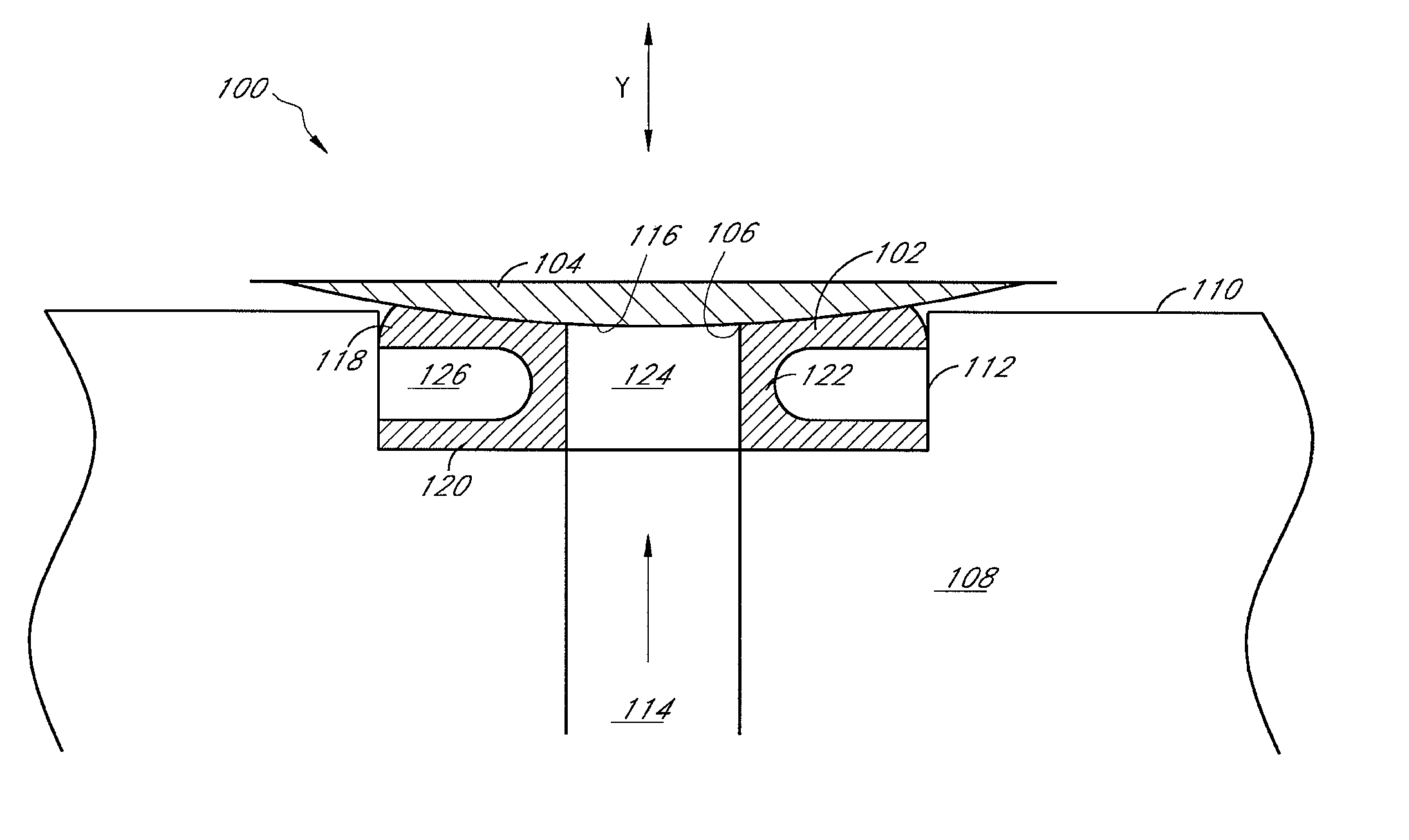
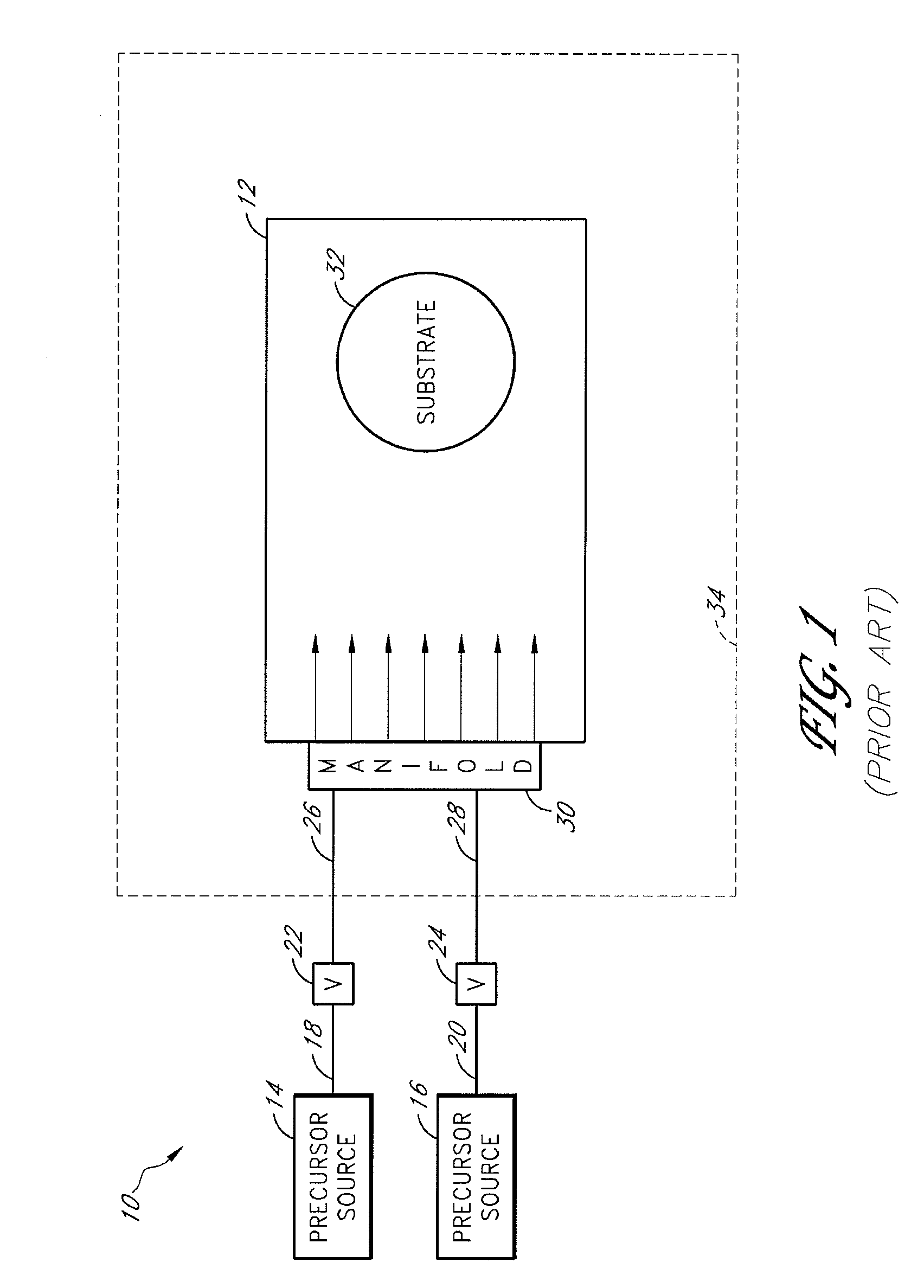
[0021]One limitation of conventional deposition equipment is that the valves of the gas delivery system must be positioned at a certain distance from the “hot zone” of the reaction chamber. The hot zone generally comprises the reaction chamber and a surrounding area that is kept at a relatively high temperature. Conventional valves would degrade or possibly even melt if positioned in the hot zone. Thus, the valves are normally positioned at a safe distance upstream of the reaction chamber, to enhance their longevity.

[0022]This limitation on the positioning of the valves of the reactant gas delivery system can lead to a significant problem. For example, during ALD, it is desirable to completely shut off the inflow of a first precursor while a second precursor is being injected into the reaction chamber, to avoid premature intermixing and CVD-type growth. However, since the valves are significantly upstream of the injection manifold or showerhead, some of the first precursor still res...


PUM

PropertyMeasurementUnit
temperaturesaaaaaaaaaa
temperatureaaaaaaaaaa

Abstract

A valve comprises a valve seat and a movable diaphragm. The valve seat defines a fluid orifice and is formed at least partially of polybenzimidazole. The diaphragm is sized and configured to bear against the fluid orifice to substantially block fluid flow through the orifice. The valve is advantageously used in a hot zone of a semiconductor processing system.

Description

BACKGROUND OF THE INVENTION[0001]1. Field of the Invention[0002]The present invention relates generally to valves for use in high temperature zones, and specifically to valves used in semiconductor equipment for controlling gas flow at high temperatures.[0003]2. Description of the Related Art[0004]High-temperature ovens, called reactors, are used to create structures of very fine dimensions, such as integrated circuits on semiconductor substrates. One or more substrates, such as silicon wafers, are placed on a substrate support inside the reaction chamber. Both the substrate and support are heated to a desired temperature. In a typical substrate treatment step, reactant gases (also referred to as precursors) are passed over the heated substrate, causing the deposition (e.g., chemical vapor deposition, or CVD) of a thin layer on the substrate. CVD is typically conducted at high temperatures, such as 250-900° C.[0005]Deposition equipment normally includes a system for delivering gas t...

Claims


Application Information

Patent Timeline
Patent Type & Authority Patents(United States)
IPC IPC(8): F16K1/42
CPCC23C16/44F16K25/005F16K7/12C23C16/45561
Inventor WHITE, CARL L.CURRY, PAUL G.
Owner ASM IP HLDG BV
Why Eureka
Try Eureka