
Valve for product-guiding processing plant

a technology for processing plants and valves, which is applied in the direction of lift valves, valve details, and valve member-seat contacts, etc., can solve the problems of affecting the service life of the sealing and affecting the service life of the sealing element. , to achieve the effect of improving the service life of the sealing element of the closure member and/or the functional reliability of the valv

Active Publication Date: 2015-10-06
PENTAIR SUDMO
View PDF11 Cites 0 Cited by
  • Summary
  • Abstract
  • Description
  • Claims
  • Application Information

AI Technical Summary

Benefits of technology

[0013]It is an object of the invention to improve a valve for a product-guiding plant, such that the service life of the sealing element of the closure member and / or the functional reliability of the valve is / are increased.

Problems solved by technology

When the closure member is transferred into the closed position, the sealing element may not be able to detach or push aside the product residues depending on the strength of the attachment of the product residues to the cylindrical inner wall of the housing portion, but instead the sealing element runs over the adhering product residues.
As the sealing element is moved along the cylindrical inner wall of the housing portion, the sliding friction of the sealing element along the cylindrical inner wall of the housing portion thus increases disadvantageously, and the movement of the sealing element over the product residues disadvantageously leads to quicker wear of the sealing element.
If the product residues are located in the region of the closure member seat, the sealing effect of the sealing element at the closure member seat is also reduced, and therefore the valve may exhibit leaks even when the sealing element is not yet worn.

Method used


Image

  • Valve for product-guiding processing plant
  • Valve for product-guiding processing plant
  • Valve for product-guiding processing plant

Examples


Embodiment Construction

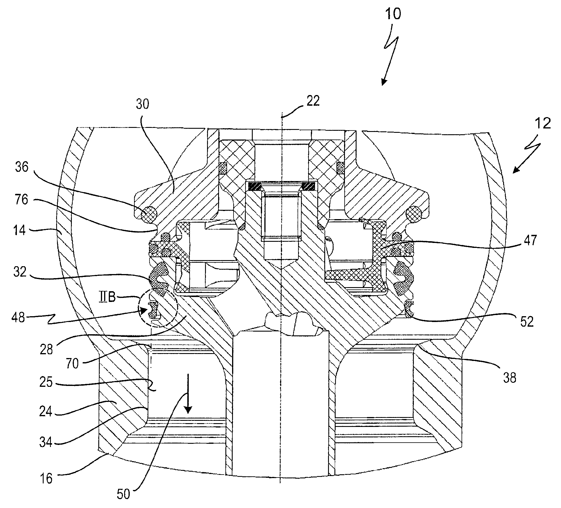
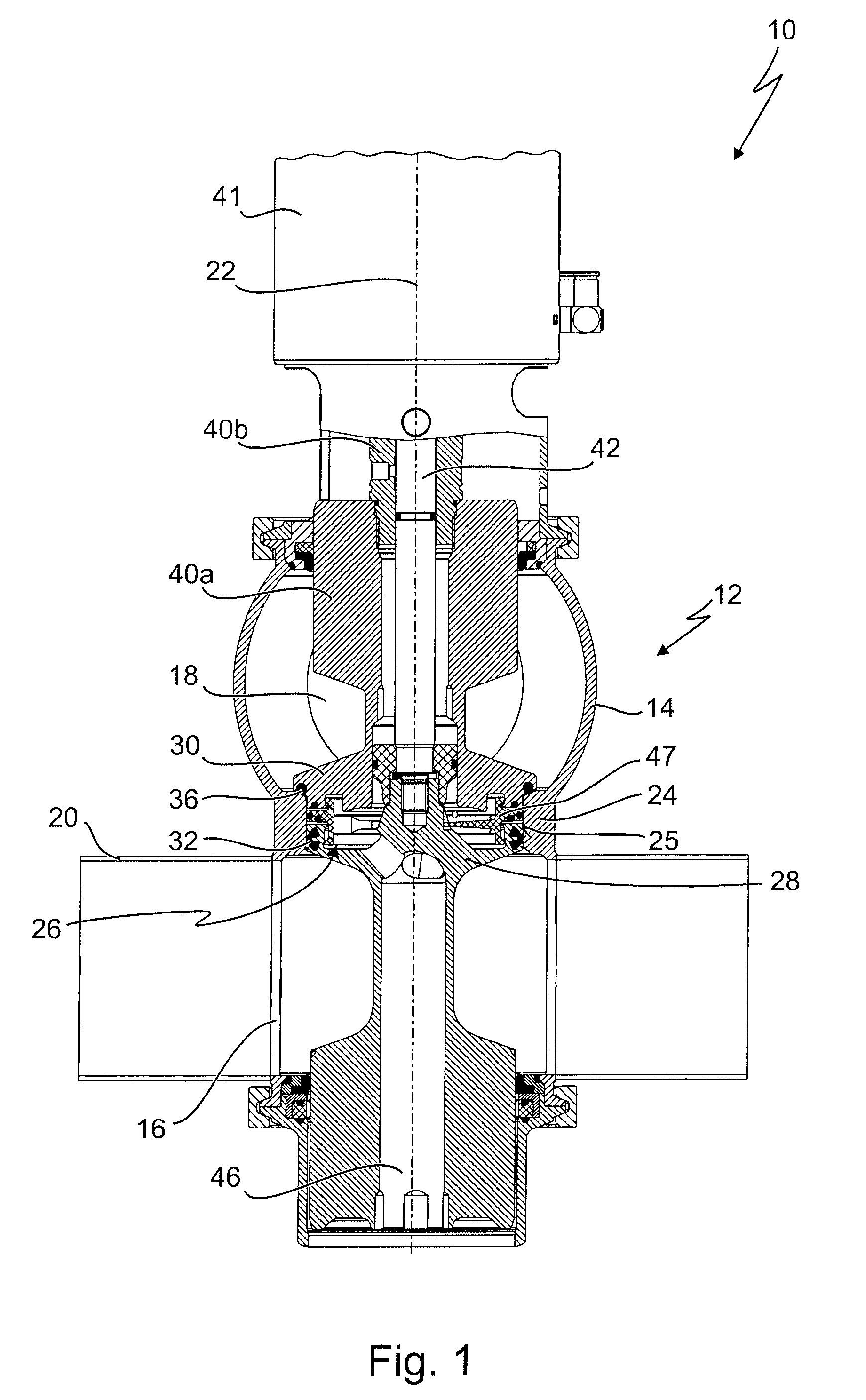
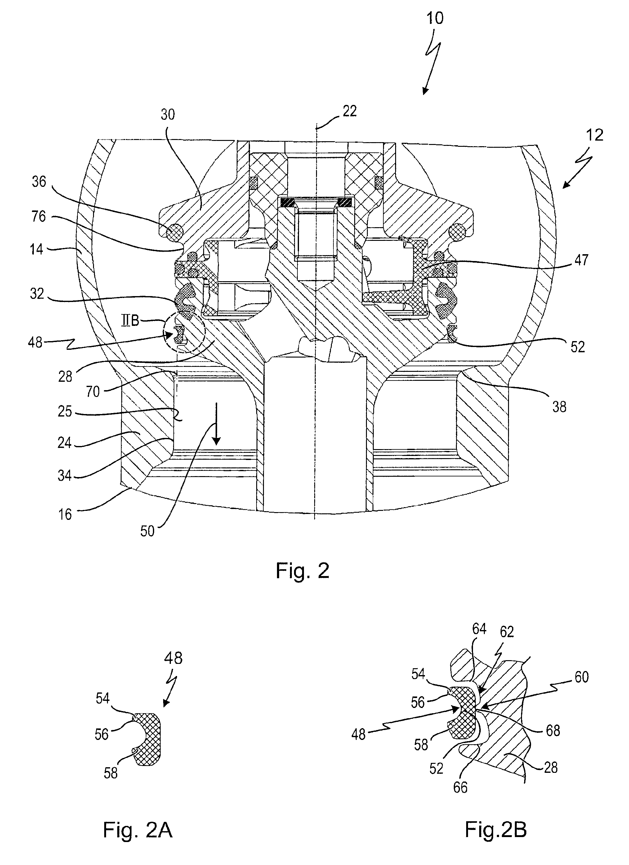
[0052]FIG. 1 illustrates a valve provided with the general reference sign 10 for a product-guiding processing plant. The valve 10 is designed as a double seat valve in the embodiment shown. FIGS. 2 to 4 show details of the valve 10 in a development according to the invention, which is not illustrated in FIG. 1.

[0053]The valve 10 is used in a food processing plant for example, in particular in a milk processing facility or in a dairy.

[0054]The valve 10 has a housing 12, which has a first housing portion 14 and a second housing portion 16. A first connection piece 18 is arranged on the first housing portion 14 for connection of a first pipeline (not illustrated) to the valve 10, and a second connection piece 20 is arranged on the second housing portion 16 for connection of a further pipeline (not illustrated) to the valve 10, the connection pieces 18 and 20 being arranged, in the exemplary embodiment shown, offset from one another by 90° with respect to a longitudinal axis 22 of the h...


PUM

PropertyMeasurementUnit
circumferenceaaaaaaaaaa
hardaaaaaaaaaa
outer circumferenceaaaaaaaaaa

Abstract

A valve for a product-guiding processing plant comprises a housing, in which a closure member and a closure member seat are arranged. The closure member seat is provided on a cylindrical inner wall of a housing portion of the housing. The closure member has a sealing element, which cooperates in a sealing manner with the closure member seat in a closed position of the closure member. The closure member is displaceable in the direction of a longitudinal axis of the housing between an open position, in which the sealing element is distanced from the closure member seat, and the closed position. The valve comprises a scraper for detaching product residues from the inner wall of the inner cylindrical housing portion, the scraper being arranged ahead of the sealing element, as viewed in the direction of closure of the closure member from the open position into the closed position, and being moved along and against the inner wall of the inner cylindrical housing portion when the closure member is displaced from the open position into the closed position.

Description

CROSS REFERENCE TO FOREIGN APPLICATION[0001]This application claims priority from German patent application No. 10 2011 116 735.1 filed on Oct. 19, 2011. The entire contents of this priority application is incorporated herein by reference.BACKGROUND OF THE INVENTION[0002]The invention generally relates to valves for use in product-guiding plants. More specifically, the invention relates to a valve, comprising a housing, in which a closure member and a closure member seat are arranged. The closure member seat being provided on a cylindrical inner wall of a housing portion of the housing, wherein the closure member has a sealing element, which cooperates in a sealing manner with the closure member seat in a closed position of the closure member. The closure member is displaceable in the direction of a longitudinal axis of the housing between an open position, in which the sealing element is distanced from the closure member seat, and the closed position.[0003]A valve of the type descr...

Claims


Application Information

Patent Timeline
Patent Type & Authority Patents(United States)
IPC IPC(8): F16K1/44F16K25/00
CPCF16K1/44F16K1/446F16K25/005
Inventor DEGER, WERNERNEUHAUSER, FRANK
Owner PENTAIR SUDMO
Learn More