Nozzle shutoff for an injection molding machine

a technology of injection molding machine and valve, which is applied in the field of valve for injector nozzle, can solve the problems of undesired leakage of pressurized thermoplastic material and undesired heat of thermoplastic material

Inactive Publication Date: 2012-10-16
MGS MFG GROUP
View PDF6 Cites 2 Cited by
  • Summary
  • Abstract
  • Description
  • Claims
  • Application Information

AI Technical Summary

Benefits of technology

[0005]The present invention provides an improved valve for an injector nozzle preventing the stringing of injection mold material from the nozzle of an injection molding nozzle after completing the filling a mold.
[0006]Specifically, the present invention is directed to an injection molding valve including a housing having a first bore extending along a length of the housing for the flow of thermoplastic to the nozzle. The housing further includes a second bore intersecting the first bore and including a groove disposed circumferentially disposed on a wall of the second bore between the first bore and outside of the housing. A rotatable member is positioned within the second bore and includes a hole therethrough. An operator is coupled to the rotatable member for rotating the rotatable member between an open position where the hole is aligned with the first bore and a closed position where the hole is perpendicular to the first bore. A port is provided in communication with the groove of the wall of the second bore. The port is configured to receive thermoplastic and deliver it to the groove to form a mold-in-place seal. The mold-in-place seal serves to prevent the stringing of thermoplastic injected through the first bore from stringing out of the valve housing through the second bore.
[0007]Thus, it is an object of at least one embodiment of the present invention to provide for the insertion of a thermoplastic resistant seal into a valve that may prevent stringing of thermoplastic material through the valve housing through use of a mold-in-place technique. The mold-in-place technique permits a low compliance material to be selected without concern for tolerances in the valve or the need to compress the seal during assembly. By using a thermoplastic material injected into the valve, the properties of the seal may better match the thermoplastic being molded in terms of expansion and adhesion to resist leakage.
[0013]Thus, it is another object of the present invention to provide a relatively simple valve construction allowing low tolerances with standard machining.
[0015]It is thus another object of the present invention to provide a simple method of injecting the thermoplastic to form the seals for the valve of the present invention.
[0017]Thus, it is yet another object of the present invention to provide a pair of seals such that thermoplastic injected through the first bore is prevented from stringing out either side of the second bore of the valve housing.

Problems solved by technology

During this period of separation, heated thermoplastic may undesirably “string” from the injector nozzle.
In this latter design, pressurized thermoplastic material can undesirably leak along the path of the valve operator producing a problem similar to that of the stringing and or preventing free operation of the valve mechanism as a result of contamination.

Method used


Image

  • Nozzle shutoff for an injection molding machine
  • Nozzle shutoff for an injection molding machine
  • Nozzle shutoff for an injection molding machine

Examples


Embodiment Construction

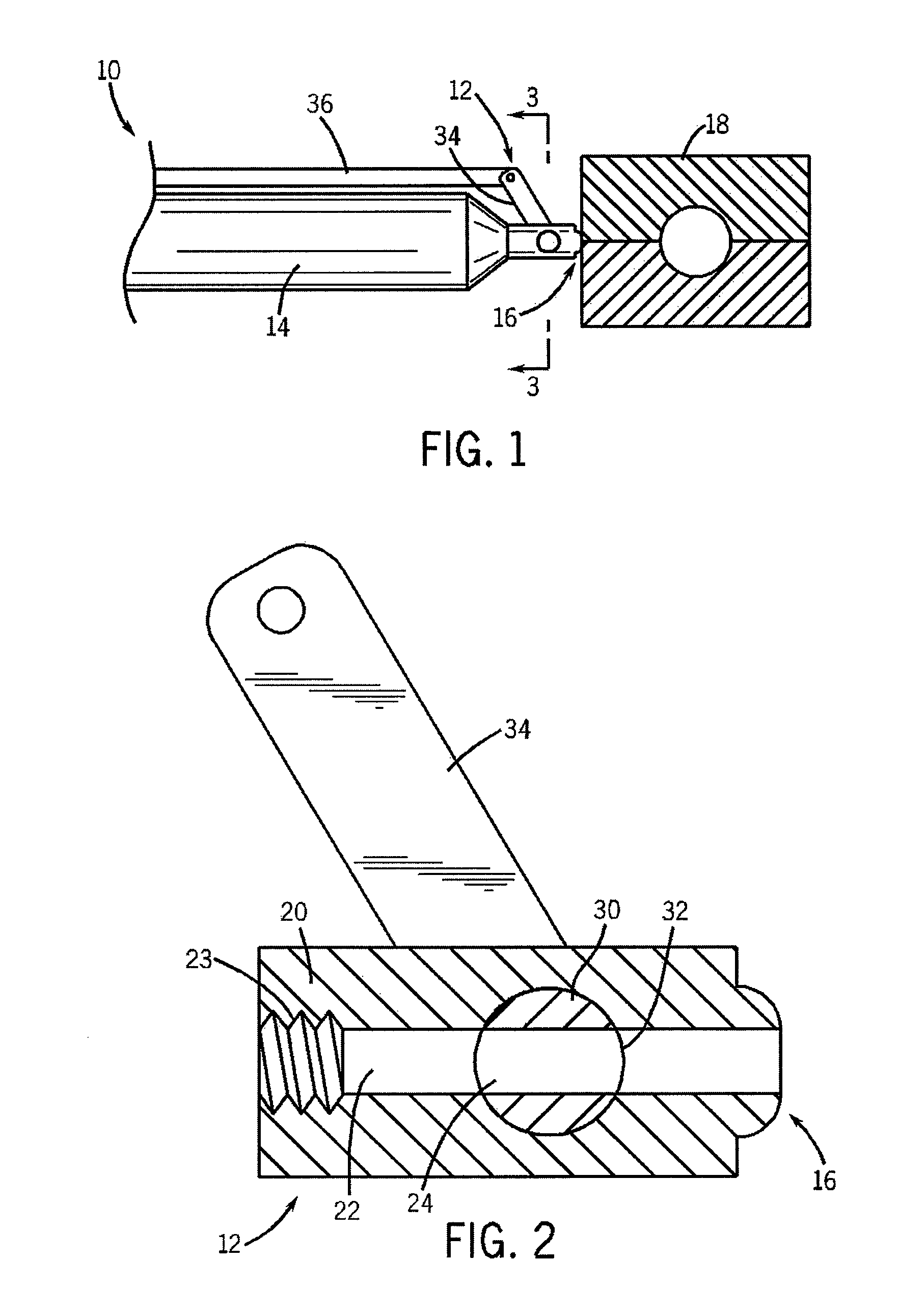
[0027]Referring now to the drawings, and initially to FIG. 1, an injection molding system 10 is equipped with the valve 12 of the present invention. Injection molding system 10 includes a injector 14 for heating and ejecting molten the thermoplastic material. The injector 14 has a threaded nozzle that is attached to valve 12 that conducts firmer plastic material from the injector 14 to a nozzle 16. Nozzle 16 is configured to abut a mold 18 and to deliver the thermoplastic material under substantially high pressures and temperatures to the mold 18. Valve 12 regulates the flow of the thermoplastic material from the injector 14 to the nozzle 16 to the mold 18.

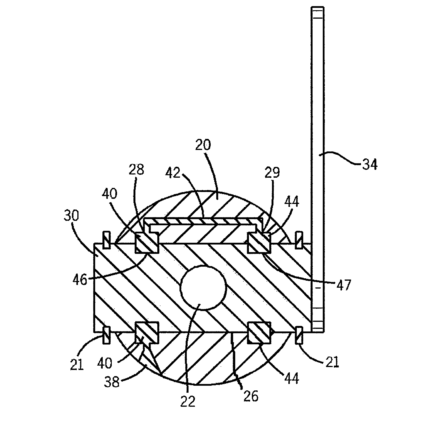
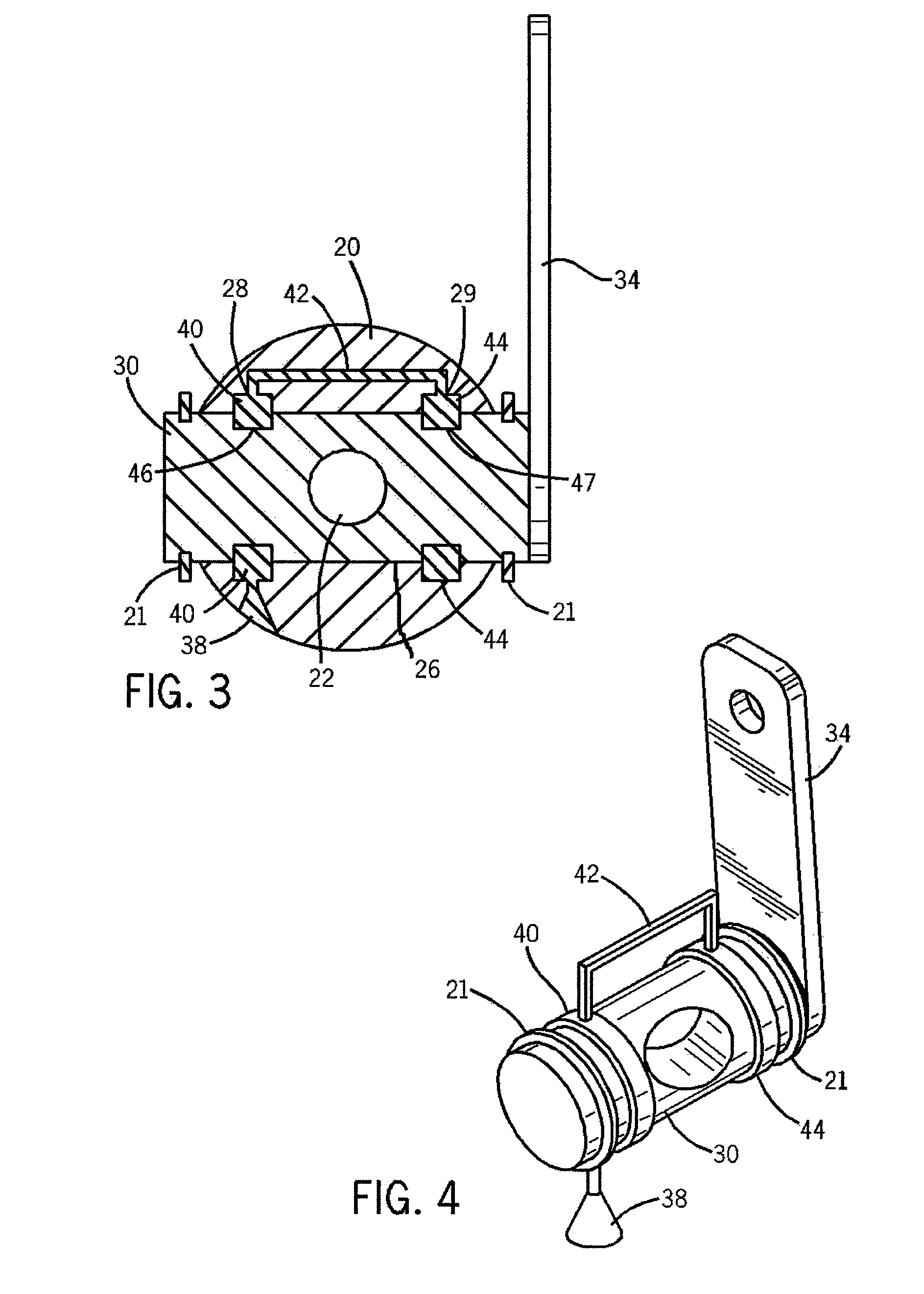
[0028]Referring now to FIGS. 2-4, the valve 12 of the present invention includes a housing 20 having a first bore 22 extending along the length of housing 20 to open at opposite ends of the housing 20 providing a channel therethrough between the injector 14 (not shown in FIG. 2) and the nozzle 16. A second bore 24 extends across t...


PUM

PropertyMeasurementUnit
lengthaaaaaaaaaa
widthaaaaaaaaaa
pressureaaaaaaaaaa

Abstract

The present invention is directed to an injection molding valve configured to prevent the leaking or stringing of injected thermoplastic from the valve. The valve includes a housing having a first bore along a length thereof and a second bore intersecting the first bore. A rotatable member is inserted through the second bore and is in communication with a lever for the actuation thereof. The rotatable member includes a hole therethrough such that when the hole is aligned with the first bore, thermoplastic may travel freely through the first bore. The second bore further includes at least one groove in communication with a port for receiving injected thermoplastic. The injected thermoplastic is hardened to form an seal therein and configured to prevent thermoplastic from leaking out of the valve housing.

Description

STATEMENT REGARDING FEDERALLY SPONSORED RESEARCH OR DEVELOPMENTCROSS REFERENCE TO RELATED APPLICATIONBACKGROUND OF THE INVENTION[0001]The present invention relates to injection molding machines, and in particular, to a valve for an injector nozzle on an injection molding machine adapted to prevent the stringing of thermoplastic residue from the nozzle.[0002]Injection molding is a manufacturing process in which heated thermoplastic is forced under pressure into a mold to produce a part. The heated thermoplastic is delivered at relatively high temperatures and under high pressure from an injector. After cooling, the hardened part is removed from the cavity of the mold and the operation is repeated, normally cycling the mold repeatedly to make one part after another.[0003]For two-shot and other sophisticated molding operations, the injector may be separated from the mold to permit mold movement or exchange. During this period of separation, heated thermoplastic may undesirably “string”...

Claims


Application Information

Patent Timeline
Patent Type & Authority Patents(United States)
IPC IPC(8): F16K5/00
CPCB29C45/23Y10T29/49412Y10T137/4358Y10T137/6058
Inventor HAHN, JOHN J.SCHMITT, LARRY A.
Owner MGS MFG GROUP
Why Eureka
Try Eureka