Electrically heated hand grip

a technology of hand grips and electric heating, which is applied in the field of hand grips, can solve the problems of not providing heat to the hands of users, stiff fingers, and unpleasant effects on the joints, fingers and hands of golfers, and achieve the effect of convenient mounting

Inactive Publication Date: 2006-02-14
MARQUIS VAUGHN JOSEPH
View PDF12 Cites 30 Cited by
  • Summary
  • Abstract
  • Description
  • Claims
  • Application Information

AI Technical Summary

Benefits of technology

[0008]It is also a further objective of the present invention to provide an electrically heated hand grip which comprises a completely, integrated hand grip or a wrapped strip grip which can be easily mounted on to the end of a shaft.

Problems solved by technology

An existing problem with conventional hand grips is that they do not provide heat to a user's hands.
The golfer is often exposed to the elements of rain, wind and cold temperatures, which can have an unpleasant effect on the joints, fingers, and hands of the golfer.
The joints and fingers become stiff and painful, thus, making it difficult for the person to securely grip the golf club.
The elements can also impact the physical properties of the golf club itself such that the hand grip of the golf club becomes hard and inflexible thereby reducing the shock absorbing and slip-inhibiting qualities of the hand grip and further degrading the player's performance.

Method used


Image

  • Electrically heated hand grip
  • Electrically heated hand grip
  • Electrically heated hand grip

Examples


second embodiment

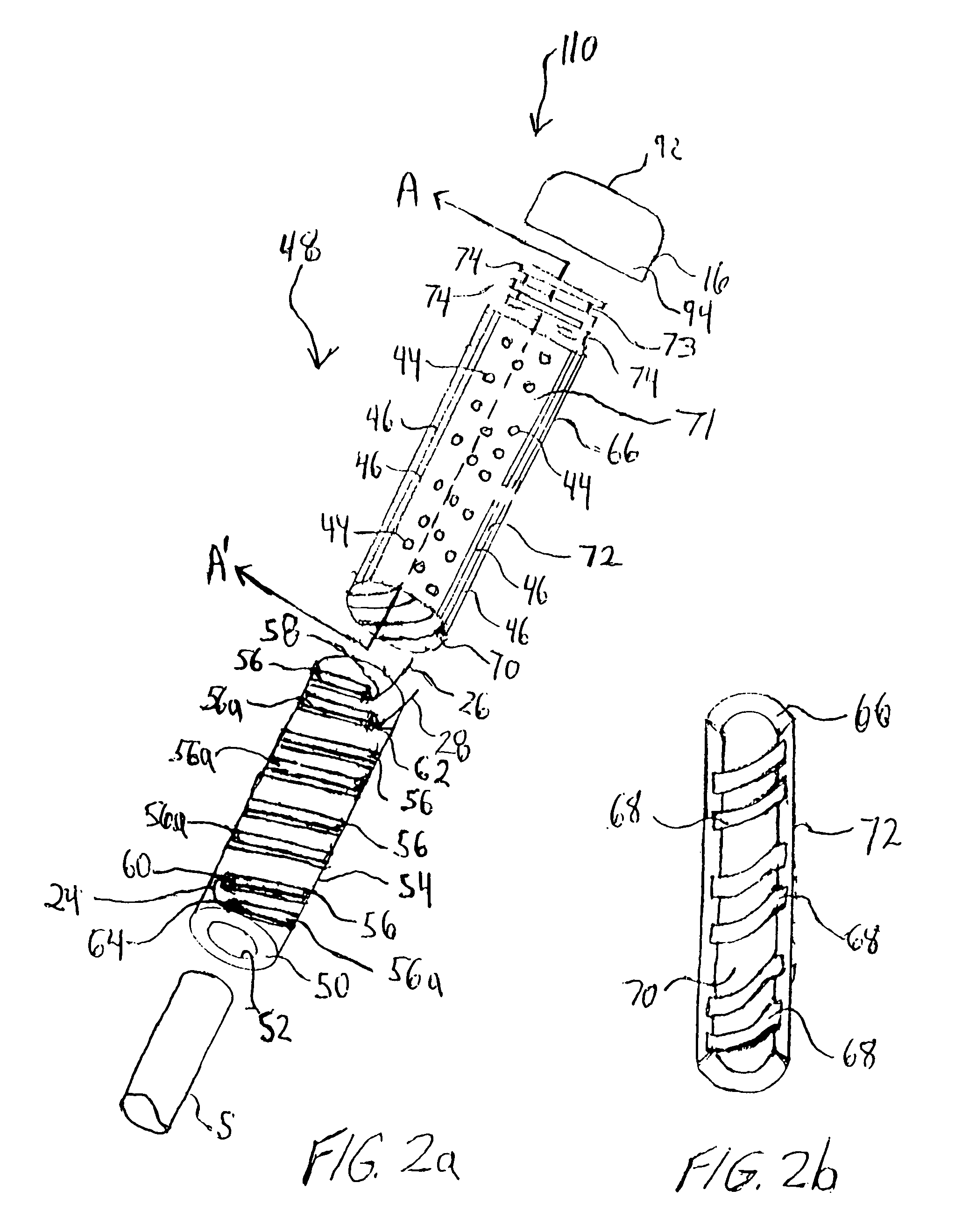
[0061]Referring to FIG. 2a there is shown an electrically heated hand grip 110, in accordance with the present invention. The electrically heated hand grip 110 includes a hand grip 48. The hand grip 48 includes an inner sleeve 50 having an interior surface 52 and an exterior surface 54 and a plurality of hollow ribs 56 and 56a. The plurality of hollow ribs 56 and 56a are helically disposed about the exterior surface 54 of the inner sleeve 50. The hollow ribs 56 and 56a can be all the same height, width and length or of differing heights, widths or lengths. The hollow ribs 56 and 56a are cylindrical, rectangular or square in shape and fabricated or formed from a plastic, foam or rubber material.

[0062]It will be appreciated that although the plurality of hollow ribs 56 and 56a are shown as being helically wrapped around the exterior surface 54 of the inner sleeve 50, the hollow ribs 56 and 56a may also extend along the longitudinal axis of the exterior surface 54 of the inner sleeve 5...

third embodiment

[0067]Referring now to FIGS. 3a and 3b, there is shown an electrically heated hand grip 210 in accordance with the present invention. The electrically heated hand grip 210 includes a hand grip 75. The hand grip 75 includes an inner sleeve 76 having an interior surface 78, an exterior surface 80 and a plurality of stubs 82. The plurality of stubs 82 are disposed about the exterior surface 80 of the inner sleeve 76. The plurality of stubs 82 may be all the same height, width or length and may be cylindrical, square or rectangular, in shape. The plurality of stubs 82 are fabricated from a plastic, rubber or foam material. In addition, each of the plurality of stubs 82 includes a hole for receiving a heating member 14, such as, electrical resistance heating wire 24.

[0068]The electrical resistance heating wire 24 is inserted into each hole of each stub 82 and is longitudinally disposed about the exterior surface 80 of the inner sleeve 76 such that the electrical resistance heating wire 2...

fourth embodiment

[0080]Referring now to FIGS. 9–13, wherein like elements are represented by the same reference numbers throughout, there is shown an electrically heated hand grip 138 in accordance with the present invention. The electrically heated hand grip 138 includes a resilient strip 140 having an inner surface 142 and an outer surface 144. The resilient strip 140 is formed from a highly durable leather, rubber, thermoplastic, thermoplastic elastomeric or synthetic material which includes vibration dampening characteristics. The resilient strip 140 includes a heating member 146 which is embedded within or attached to the inner surface 142 of the resilient strip 140 so as to form a heating strip 148.

[0081]The heating member 146 comprises any one of an electrical resistance heating wire, etched-foil, a flexible printed circuit heater or a flexible carbon fiber heater for generating heat, all of which are well known in the art and do not require further explanation herein. Preferably the heating ...


PUM


Abstract

The electrically heated hand grip includes a hand grip, a heating member disposed within the hand grip, an end cap assembly removably attached to the hand grip, and an electrical switch coupled to a power source for controlling the supply of current to the heating member. The end cap assembly includes a receptacle for receiving the power source and an electrical connecting means. The end cap assembly may include a light-emitting diode and a charging means. In an alternative embodiment, the electrically heated hand grip includes a resilient strip having a heating member attached to an interior surface of the resilient strip to form a heating strip. The heating strip is spirally wrapped about a grip-receiving portion of a shaft. An end cap assembly is coupled to the end of a shaft to secure a portion of the heating strip. The heated hand grip can include a sleeve which is inserted on the end of a shaft and the heating strip is spirally wrapped about the sleeve.

Description

FIELD OF THE INVENTION[0001]The present invention relates to hand grips and, more particularly to an electrically heated hand grip for sporting equipment, tools and the like.BACKGROUND OF THE INVENTION[0002]Most hand grips used on sporting equipment and tools are designed to provide a cushion for shock absorbing or insulating qualities. In one example, conventional hand grips for golf clubs generally include integral grips and wrapped strip grips. The integral grip includes one or more pieces that are molded from a rubber or plastic material and joined together to form a complete one-piece hand grip, which is easily mounted or inserted, on to the end of a shaft. The wrapped strip grip may include an inner sleeve which is inserted on to the end of a shaft and a resilient strip which is spirally wrapped and secured around the exterior surface of the inner sleeve. The resilient strip is generally made of leather, rubber, foam or a plastic material.[0003]An existing problem with convent...

Claims


Application Information

Patent Timeline
Patent Type & Authority Patents(United States)
IPC IPC(8): B60L1/02
CPCA01K87/085A63B49/08A63B53/14A63B59/0014A63B59/0029A63C11/222B25G1/00A63B59/0033A63B2225/64A63B59/12A63B2057/0093A63C2203/12A63B59/0092A63B59/70A63B60/06A63B60/08A63B60/10A63B60/14A63B60/16A63B60/54A63B2057/605A63B2102/22
Inventor MARQUIS, VAUGHN JOSEPH
Owner MARQUIS VAUGHN JOSEPH
Why Eureka
Try Eureka