AI technical title is built by PatSnap AI team. It summarizes the technical point description of the patent document.
a technology of electric heat sealing and heat sealing plate, which is applied in the direction of ohmic-resistance heating, ohmic-resistance heating details, chemistry apparatus and processes, etc., can solve the problems of accidental damage to the heat sealer, no safety control means for electric heat sealing,
Inactive Publication Date: 2006-02-14
XEROX CORP
View PDF3 Cites 11 Cited by
Summary
Abstract
Description
Claims
Application Information
AI Technical Summary
This helps you quickly interpret patents by identifying the three key elements:
Problems solved by technology
Method used
Benefits of technology
Problems solved by technology
However, these electric heat sealers have no safety control means.
When an electric heat sealer is touched by an external force, the sealing mechanism may be electrically connected to produce heat, potentially causing an accident to occur.
Another problem with conventional electric heat sealers is that it is often necessary to take two “swipes” at a plastic bag to seal the bag with the sealer.
Method used
Image
Click on the blue label to locate the original text in one second.
Reading with bidirectional positioning of images and text.
Examples
Embodiment Construction
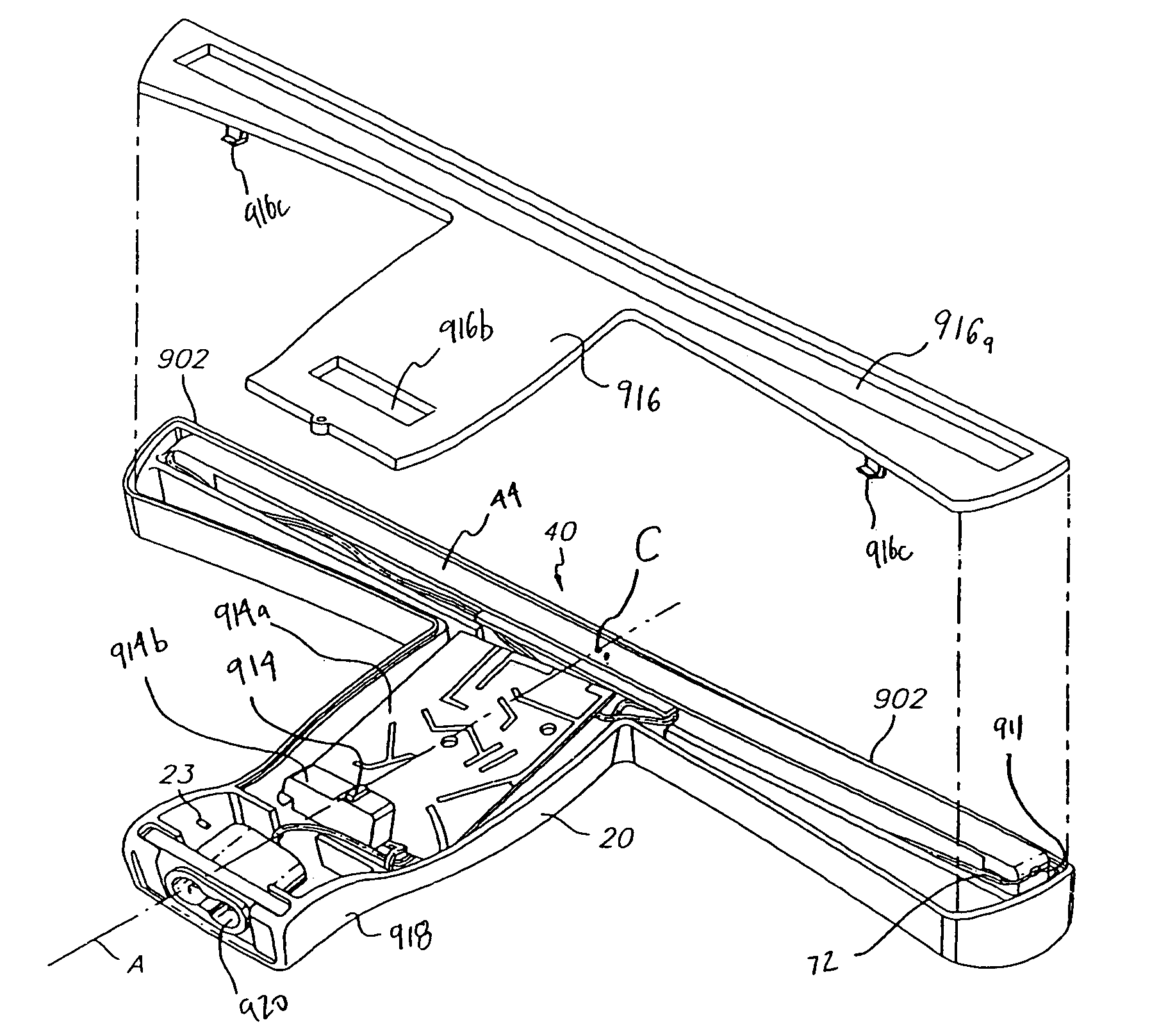
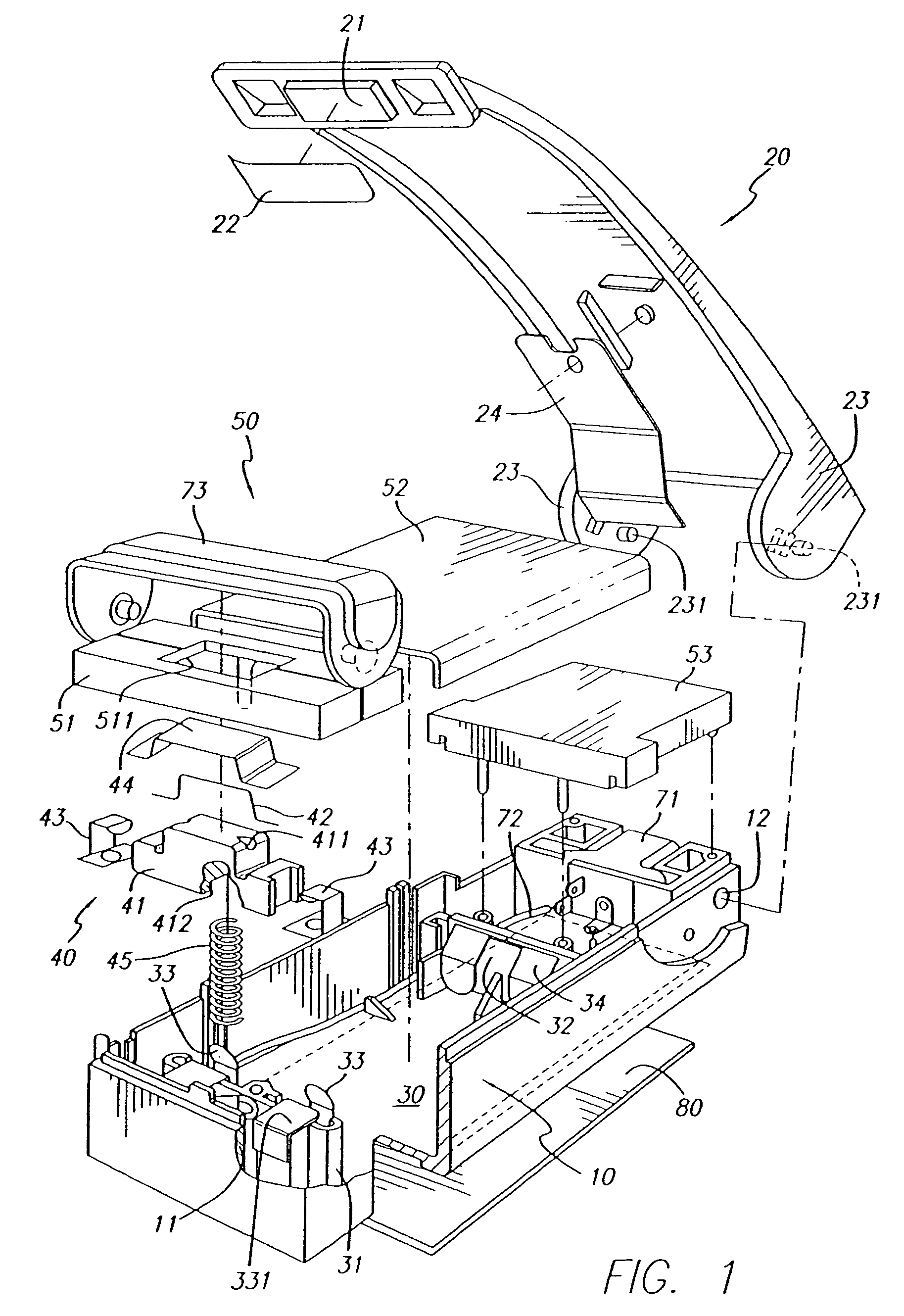
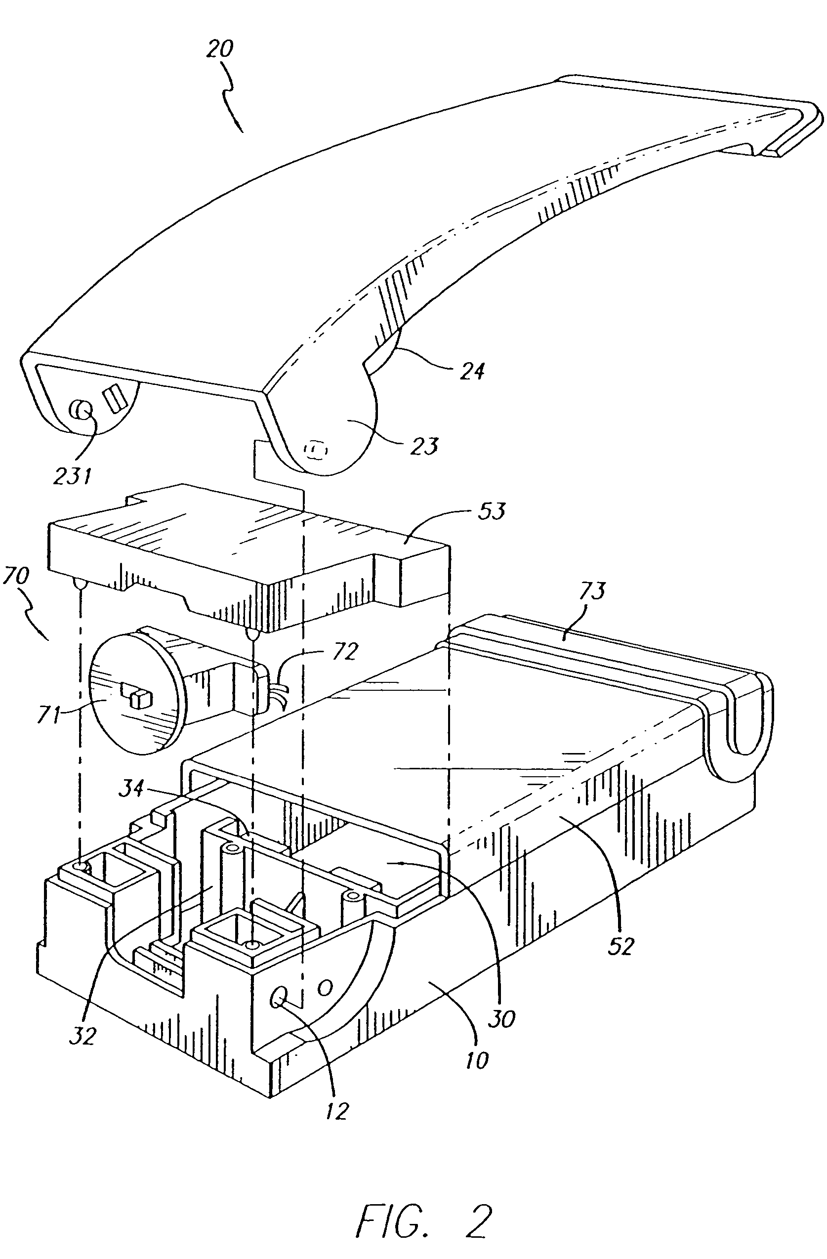
[0007]In accordance with one preferred aspect of the present invention, there is provided an electric heat sealer comprising a casing, a battery chamber, a spring holder, a sealing mechanism, a press bar, and a safety device. The casing holds the battery chamber, the spring holder, the sealing mechanism and the safety device on the inside. The battery chamber comprises a front upright support; a rear upright support; a first front terminal plate and a second front terminal plate respectively mounted on the front upright support; a pair of rear terminal plates respectively mounted on the rear upright support; a first metal contact plate mounted on the front upright support and connected the first front terminal plate; and a second metal contact plate mounted on the front upright support and spaced from the second terminal plate by a gap. The second terminal plate is forced into contact with the second metal contact plate when a battery set is installed in the battery chamber. The spr...
PUM
Property
Measurement
Unit
resistance
aaaaa
aaaaa
resistance
aaaaa
aaaaa
resistance
aaaaa
aaaaa
Abstract
An electric heat sealer including a casing having a first pair of extensions extending outwardly therefrom, a press bar pivotally connected to said casing, the press bar having a second pair of extensions extending outwardly therefrom, at least one sealing mechanism mounted in the press bar or the casing and a source of current for energizing the heating wire. The press bar is normally biased above the casing and the at least one sealing mechanism includes a heating wire.
Description
[0001]This is a divisional of U.S. patent application Ser. No. 10 / 072,293, filed Feb. 6, 2000, now U.S. Pat. No. 6,770,849, which is a continuation-in-part of U.S. patent application Ser. No. 09 / 495,999, filed Feb. 1, 2000, now U.S. Pat. No. 6,335,515, and Ser. No. 09 / 208,256, filed Dec. 9, 1998, now U.S. Pat. No. 6,326,594, both of which are continuations-in-part of U.S. patent application Ser. No. 09 / 189,359, filed Nov. 9, 1998, now U.S. Pat. No. 6,232,579, which is a continuation-in-part of U.S. patent application Ser. No. 08 / 917,358 filed on Aug. 26, 1997, now U.S. Pat. No. 5,854,466, the disclosures of which are incorporated in their entireties herein by reference.FIELD OF THE INVENTION[0002]The present invention relates to an electric heat sealer, and more particularly to an electric heat sealer which can be controlled to break the electric circuit when the apparatus is not in use, so as to prevent an electric connection by a false action.BACKGROUND OF THE INVENTION[0003]A var...
Claims
Application Information
Patent Timeline
Application Date:The date an application was filed.
Publication Date:The date a patent or application was officially published.
First Publication Date:The earliest publication date of a patent with the same application number.
Issue Date:Publication date of the patent grant document.
PCT Entry Date:The Entry date of PCT National Phase.
Estimated Expiry Date:The statutory expiry date of a patent right according to the Patent Law, and it is the longest term of protection that the patent right can achieve without the termination of the patent right due to other reasons(Term extension factor has been taken into account ).
Invalid Date:Actual expiry date is based on effective date or publication date of legal transaction data of invalid patent.

