Apparatus for manipulating pre-sterilized components in an active sterile field
What is Al technical title?
Al technical title is built by PatSnap Al team. It summarizes the technical point description of the patent document.
a technology of pre-sterilized components and sterile field, which is applied in the directions of liquid handling, applications, instruments, etc., can solve the problems of product degradation, inability to sterilize after assembly, and inability to sterilize the integrated product after assembly
Inactive Publication Date: 2005-07-28
C R F SOC CONSORTILE ER AZIONI +1
View PDF25 Cites 9 Cited by
Summary
Abstract
Description
Claims
Application Information
AI Technical Summary
This helps you quickly interpret patents by identifying the three key elements:
Problems solved by technology
Method used
Benefits of technology
[0019] Other advantages and aspects of the present invention will become apparent upon reading the following detailed description of the invention.
Problems solved by technology
One significant restraint on the design, development, and manufacture of such products has been the fact that certain desirable products would include portions or components which are mutually incompatible from a sterilization standpoint.
The integral product, however, cannot be sterilized after assembly because not all of the components may be subjected to the same form of sterilization.
The drug component, on the other hand, may not be sterilized with either gas or radiation-gas sterilization would be ineffective to sterilize a sealed drug, while exposing the drug to radiation may lead to product degradation or otherwise have a deleterious effect on the drug.
While these type of high energy systems function well, when compared to the present invention they can be considered very large (sometimes requiring a separate room with thick walls of lead shielding), more expensive, and somewhat product-specific.
Method used
Image
Click on the blue label to locate the original text in one second.
Reading with bidirectional positioning of images and text.
Examples
Embodiment Construction
[0030] While the invention is susceptible of embodiment in many different forms, this disclosure will describe in detail preferred embodiments of the invention with the understanding that the present disclosure is to be considered as an exemplification of the principles of the invention and is not intended to limit the broad aspect of the invention to the embodiments illustrated.
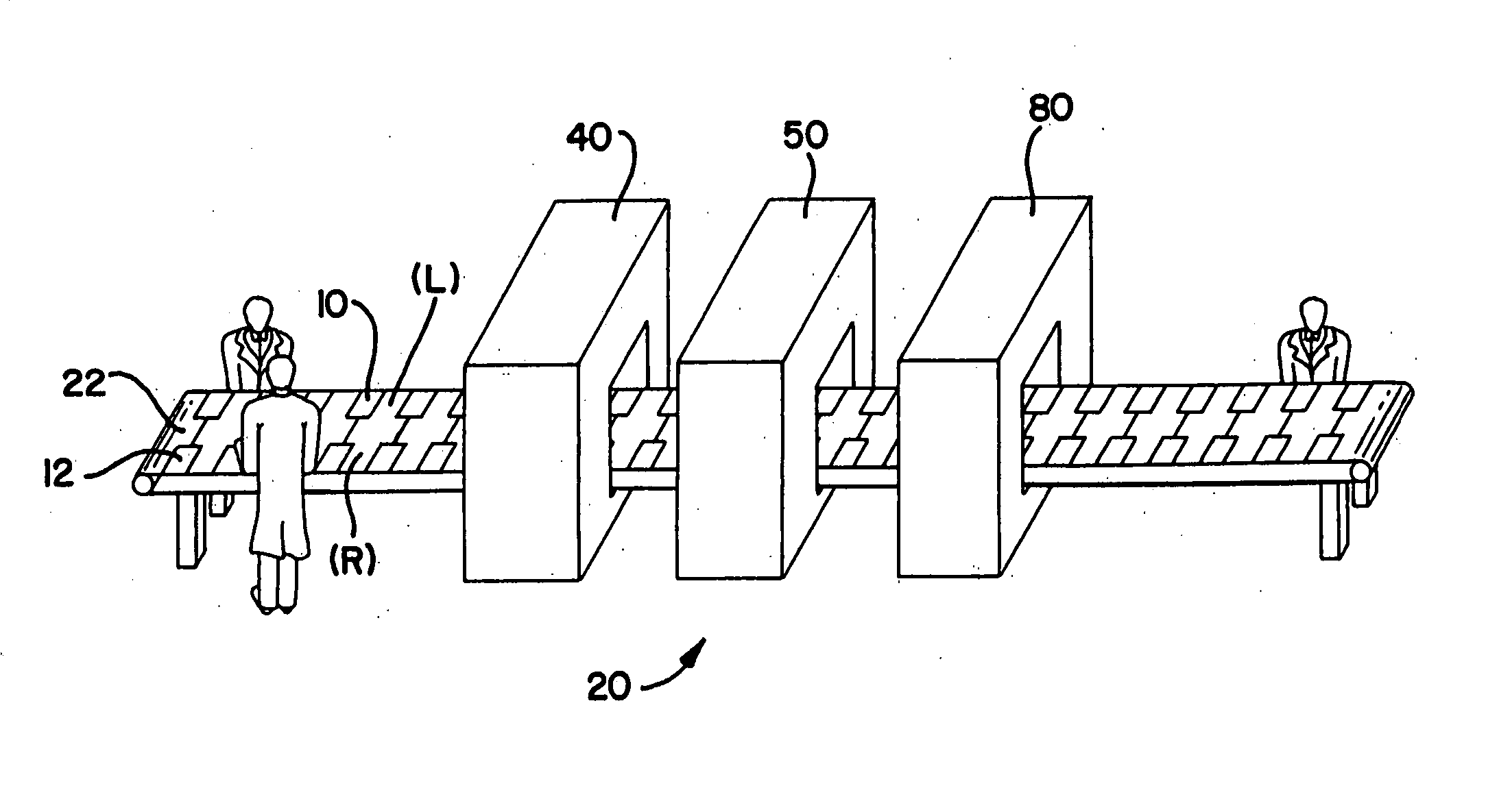
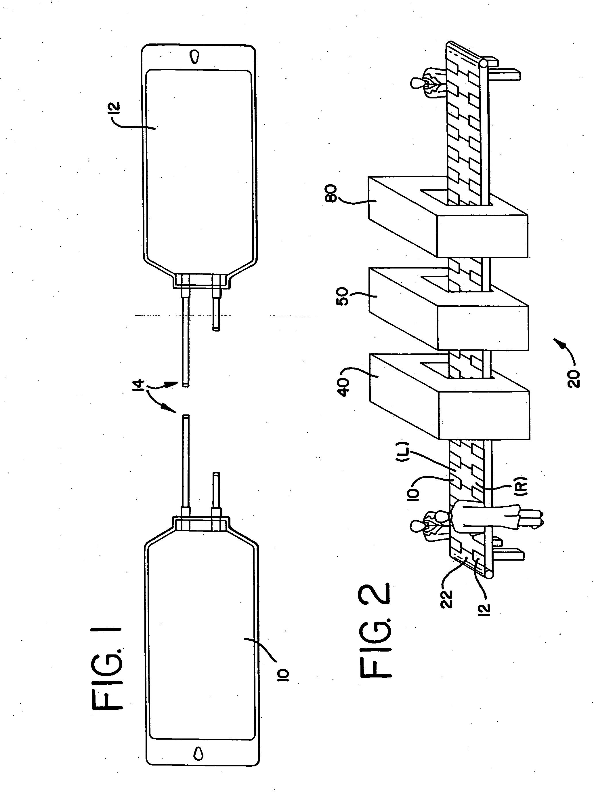
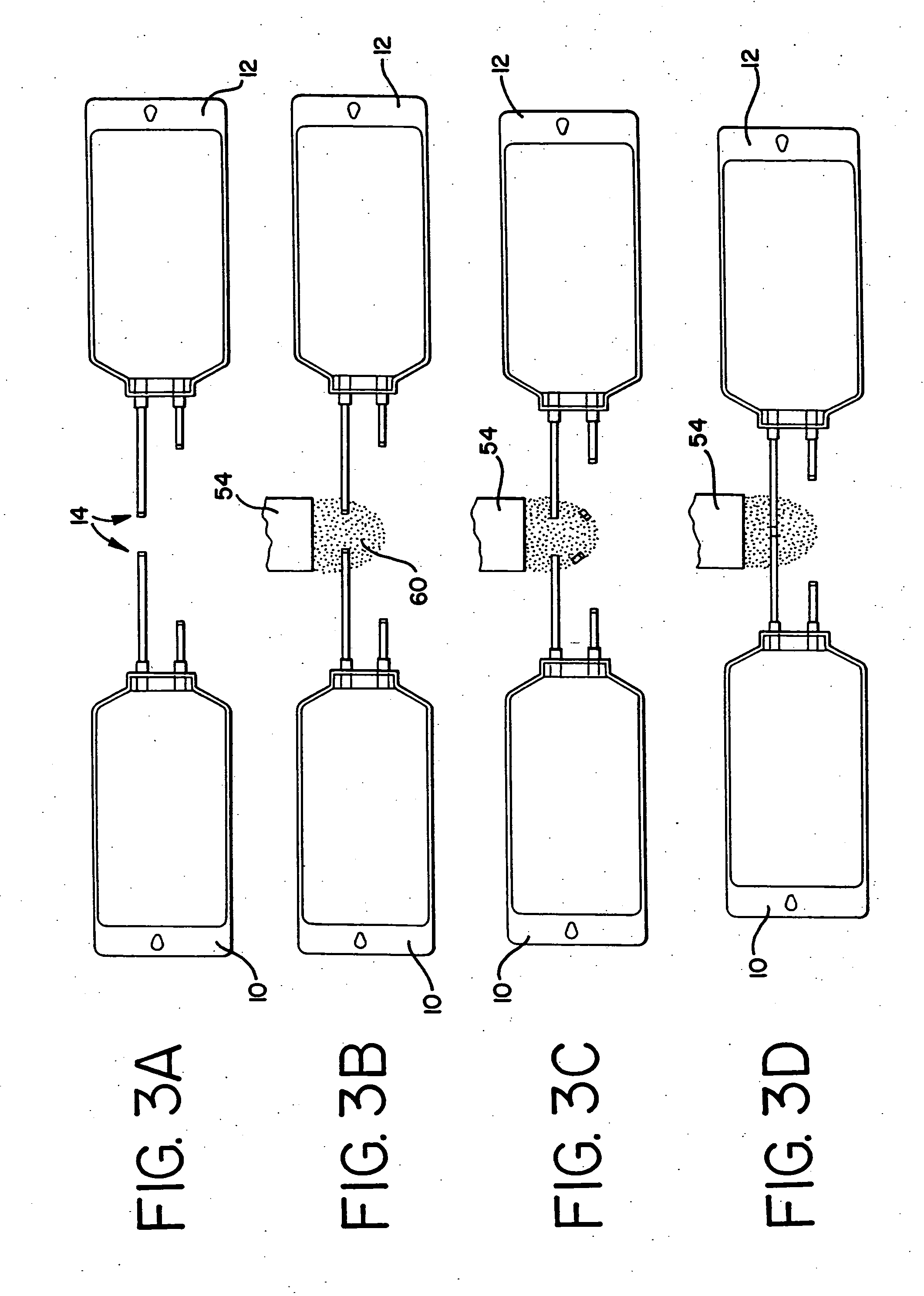
[0031] The present invention involves methods and apparatus for joining plastic components in a sterile manner. The term “joining” in this application includes the processes of: 1) connecting components, where a fluid pathway is created at the time of joining; 2) assembling components, where a fluid pathway is not complete at joining, but may be completed at a later time; and, 3) filling at least one component from a bulk container. Particularly, the invention permits the joining together of tubing to container, tubing to tubing, tubing to connector, vial to connector, container to connector, and even sheet...
PUM
Property
Measurement
Unit
Energy
aaaaa
aaaaa
Energy
aaaaa
aaaaa
Energy
aaaaa
aaaaa
Abstract
The connection, assembly, or fill of two or more pre-sterilized components 10, 12 having at least one terminal end 14 each for attachment to another component, and an apparatus for performing such a connection, while maintaining the sterility of the components is disclosed. The resulting connection is made permanent by bonding the contacting components 10, 12 together using either a solvent bonding technique, a radio frequency sealer, a heat sealer, or any other suitable process. The connection is preferably made within an active sterile field 60. Using a low-voltage electron beam instrument 54, such as the MIN-EB™, a suitable sterile field sphere can be created. The terminal ends 14 of the multiple components 10, 12 remain within the sterile field sphere 60 until the possibility of contamination within the sealed components is significantly reduced to industry acceptable standards.
Description
RELATED APPLICATIONS [0001] This application is a continuation application and claims the benefit of co-pending U.S. application Ser. No. 10 / 365,793, filed Feb. 13, 2003, which is a continuation application of U.S. application Ser. No. 09 / 294,964, filed Apr. 20, 1999. This application also claims the benefit of co-pending U.S. application Ser. No. 09 / 970,580, filed Oct. 4, 2001, which is a divisional application of U.S. application Ser. No. 09 / 294,964, filed Apr. 20, 1999. Both applications are expressly incorporated herein by reference.TECHNICAL FIELD [0002] This invention relates generally to the methods and apparatus for connecting, assembling, and filling pre-sterilized medical components in a sterile field. More particularly, the present invention relates to the use of a low energy electron beam field to create a sterile atmosphere in which connecting, assembling, or filling of pre-sterilized medical components, such as solution delivery sets, medical tubing, drug vials, medica...
Claims
Application Information
Patent Timeline
Application Date:The date an application was filed.
Publication Date:The date a patent or application was officially published.
First Publication Date:The earliest publication date of a patent with the same application number.
Issue Date:Publication date of the patent grant document.
PCT Entry Date:The Entry date of PCT National Phase.
Estimated Expiry Date:The statutory expiry date of a patent right according to the Patent Law, and it is the longest term of protection that the patent right can achieve without the termination of the patent right due to other reasons(Term extension factor has been taken into account ).
Invalid Date:Actual expiry date is based on effective date or publication date of legal transaction data of invalid patent.
Patent Type & Authority Applications(United States)