
Baton

a self-defense and a weapon technology, applied in the field of a weapon, can solve the problems of carrying a gun, personal self-defense against criminal attacks is often problematic, and criminal attacks are deadly serious, and achieve the effect of facilitating the ejection of sprays

Inactive Publication Date: 2006-02-21
LIGHTSTICK PARTNERS
View PDF6 Cites 12 Cited by
  • Summary
  • Abstract
  • Description
  • Claims
  • Application Information

AI Technical Summary

Benefits of technology

"The present invention is a baton suitable for self-defense that has several technical effects. Firstly, it allows for the securing of various attachments to it, making it more versatile and easier to use. Secondly, it can be grasped underhanded with the thumb positioned over a trigger, allowing for quick and effective use in a self-defense situation. Thirdly, it permits the release of a lock and actuation of a trigger in one simple motion, making it simple for users to use. Fourthly, it allows for the ejection of incapacitating spray at an upward angle, making it more effective as a blunt instrument for thrusting into the body of an assailant, rendering them incapacitated."

Problems solved by technology

Personal self-defense against criminal attack is often problematic, particularly for women, as physical size and strength are important factors because cowardly criminals prey on those weaker than themselves.
Further, criminals often resort to the use of weapons, which makes a criminal attack deadly serious.
Although very effective, carrying a gun presents several problems.
First, many states in the United States and many countries prohibit the carrying of guns by their law-abiding citizens.
Thus, an armed citizen merely seeking to defend herself becomes a criminal.
Second, a gun turns any encounter into a potentially lethal one for the intended victim as well as the criminal.
Various devices currently exist that eject incapacitating spray; unfortunately, such devices are often difficult to operate in that they include complicated safeties and are aimed in a manner that places the device near the user's face, which results in the potential spraying of the user as well as the criminal assailant.

Method used


Image

  • Baton
  • Baton
  • Baton

Examples


first embodiment

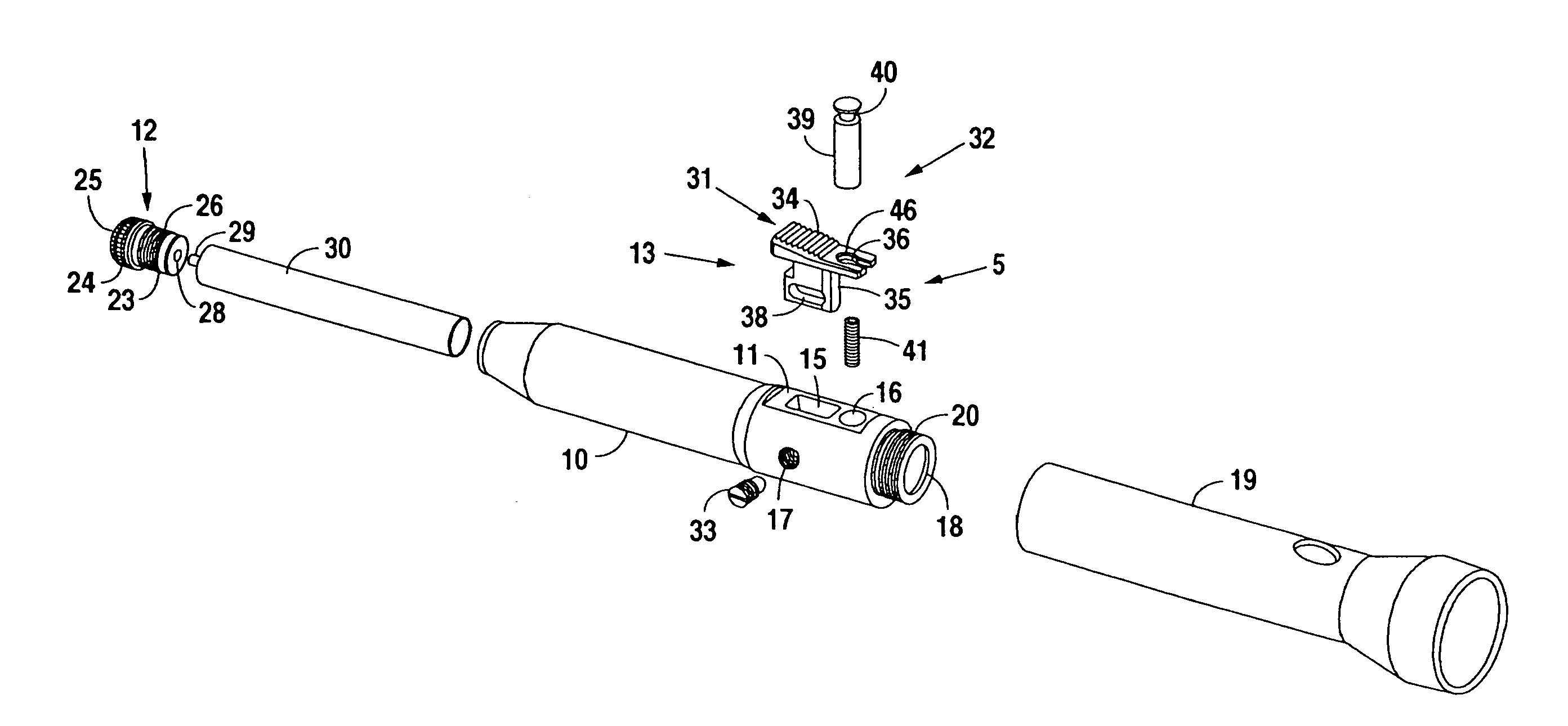
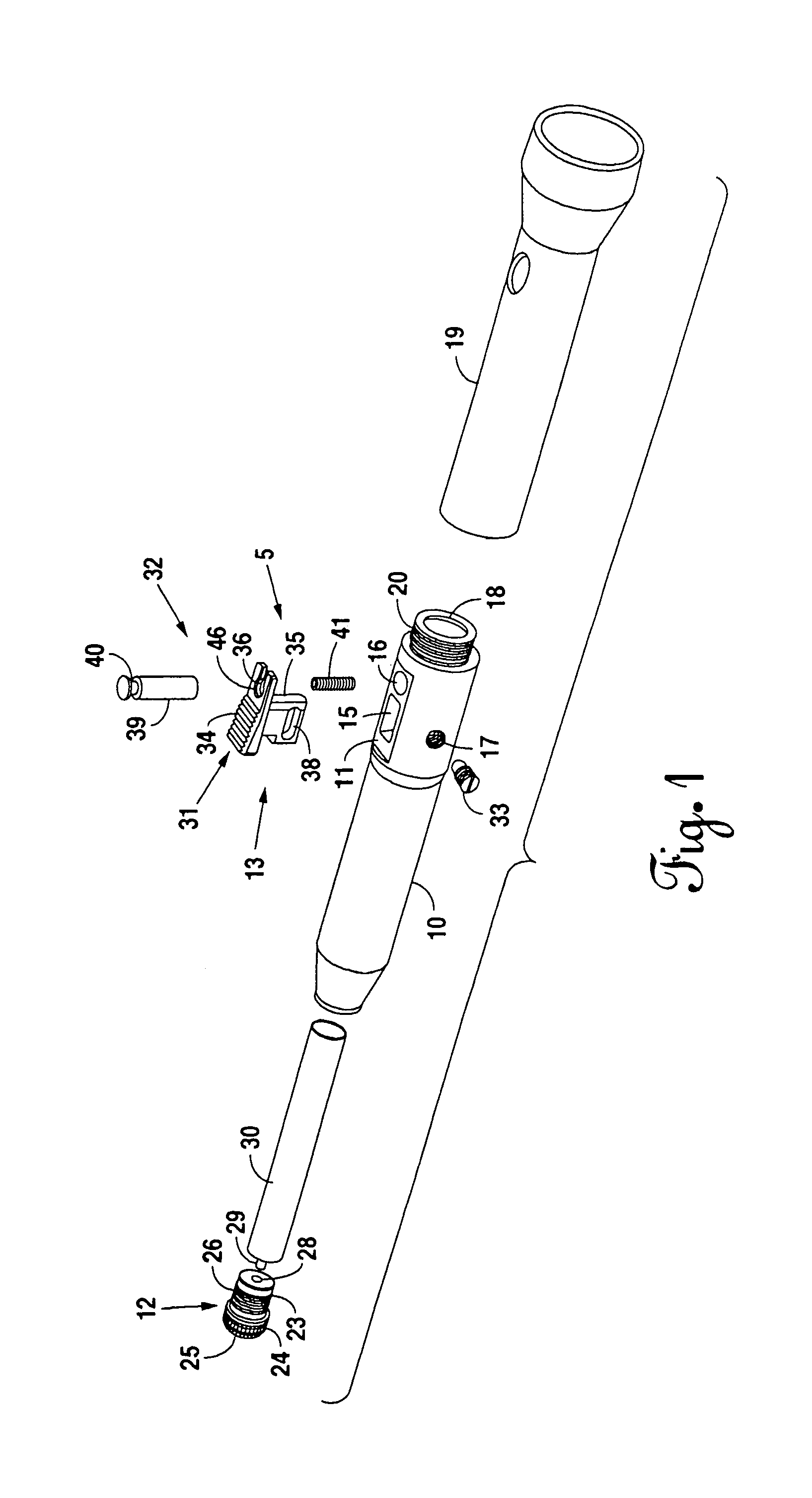
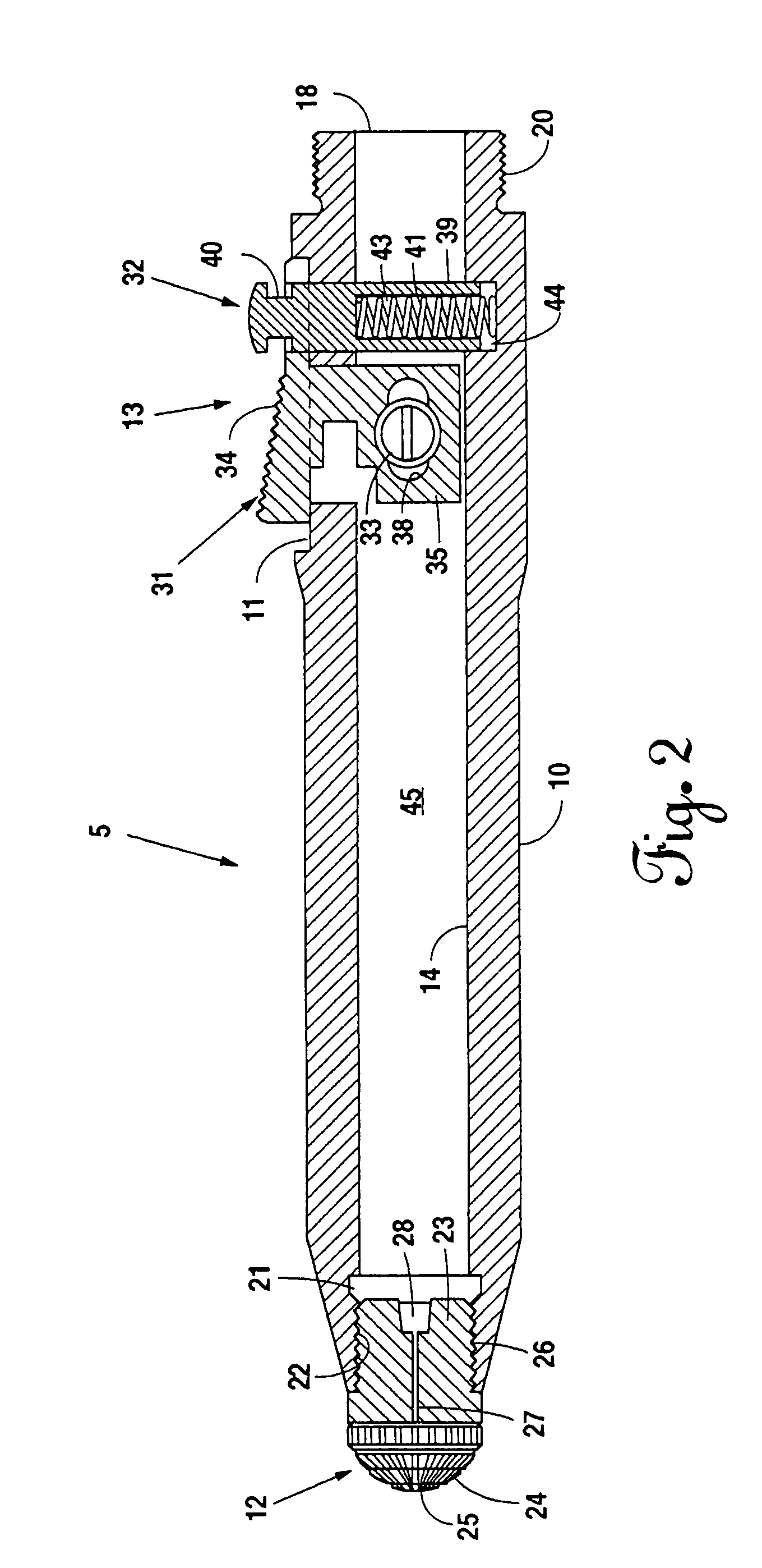
[0036]The trigger 13 is movable between a locked or unfired position and a released or fired position and includes an actuator 31, a lock 32, and a pin 33. The actuator 31 includes an activation member 34 having a ramped and knurled surface and including an aperture 36 having a detent 46 at its upper portion. The actuator 31 further includes an engaging member 35 having a slot 38 therein. The lock 32 includes a locking member 39, having a cavity 43 therein and a groove 40 thereabout. The lock 32 further includes a biasing mechanism, which in this first embodiment is a spring 41, although any suitable biasing mechanism may be used.

[0037]The spring 41 fits within the cavity 43, and the locking member 39 via the groove 40 passes through an opening 37 into the aperture 36 until the locking member 39 resides within a front portion of the aperture 36. The detent 46 of the aperture 36 engages the lower surface of the locking member 39 defining the groove 40 to maintain the locking member 3...

second embodiment

[0043]The nozzle 52 includes a body 61 terminating in a tip 62. The tip 62 may include knurls or protrusions. The body 61 is adapted to fit within the front portion 59 of the bore 55, and the tip 62 abuts the front edge of the body 51. In this second embodiment, the body 61 of the nozzle 52 includes threads 63 that engage the threads 60 to facilitate securing of the nozzle 52 to the body 51. The nozzle 52 includes a passageway 64 therethrough that facilitates the delivery of an incapacitating spray through the nozzle 52. Further, the nozzle 52 includes a cavity 65 in communication with the passageway 64. The cavity 65 receives therein a delivery tube of an incapacitating spray canister to align the canister with the nozzle 52 and facilitate the release of incapacitating spray into the passageway 64.

[0044]The trigger 53 is movable between an unfired position and a fired position. The trigger 53 includes an actuator member 66 and an engaging member 67. The actuator member 66 includes ...

third embodiment

[0050]The trigger 103 is movable between a locked or unfired position and a released or fired position and includes an actuator 120, a lock 121, and a securing member 122. The actuator 120 includes an activation member 123 having a ramped surface and including apertures 125 and 126 and a securing surface 129. The actuator 120 further includes an engaging member 124 having a cavity 127 and a removed portion 128. The lock 121 includes a locking member 130, having a cavity 131 therein and a groove 132 thereabout. The lock 121 further includes a biasing mechanism, which in this third embodiment is a spring 133, although any suitable biasing mechanism may be used.

[0051]The engaging member 124 of the actuator 120 passes through the aperture 105 and resides within the bore 104 to block the bore 104 and define a chamber that receives the canister 118 therein. The activation member 123 slides into the base 107, and the securing surface 129 engages an underneath edge of the base 107 to mainta...


PUM


Abstract

A baton suitable for use in self-defense includes a body adapted to receive a canister of spray therein, a nozzle securable to the body and adapted to receive spray therethrough, and a trigger mounted on the body. The trigger mounts on the body in a location that permits grasping of the body underhanded with the thumb positioned over the trigger to permit movement of the trigger from an unfired position to a fired position that facilitates ejection of spray from the canister through the nozzle. The trigger includes an actuator and a lock coupled therewith. One motion performed with the thumb releases the lock and moves the actuator from the unfired position of the trigger to the fired position of the trigger.

Description

CROSS-REFERENCES TO RELATED APPLICATION[0001]This application is a continuation of application Ser. No. 09 / 970,095 filed Oct. 03, 2001, now U.S. Pat. No. 6,786,368, which is a continuation-in-part of application Ser. No. 09 / 850,308, which was filed May 7, 2001, now abandoned.BACKROUND OF THE INVENTION[0002]1. Field of the Invention[0003]The present invention relates to apparatus utilized in self-defense and, more particularly, but not by way of limitation, to a baton suitable for use in self-defense.[0004]2. Description of the Related Art[0005]Personal self-defense against criminal attack is often problematic, particularly for women, as physical size and strength are important factors because cowardly criminals prey on those weaker than themselves. Further, criminals often resort to the use of weapons, which makes a criminal attack deadly serious.[0006]To counterbalance size and strength considerations as well as an armed criminal, law-abiding citizens often also arm themselves to f...

Claims


Application Information

Patent Timeline
Patent Type & Authority Patents(United States)
IPC IPC(8): B65D83/00B67D7/84F41B15/02F41H9/10
CPCF41H9/10F41B15/02
Inventor CELLINI, VITOMARTIN, RICHARD W.
Owner LIGHTSTICK PARTNERS
Learn More