
Ejecting method and ejecting apparatus

a technology of ejecting method and ejecting apparatus, which is applied in the direction of non-linear optics, instruments, printing, etc., can solve the problems of non-uniform translucency of color filters, increased manufacturing costs, and complicated manufacturing processes of photolithography methods

Inactive Publication Date: 2006-01-31
KATEEVA
View PDF8 Cites 22 Cited by
  • Summary
  • Abstract
  • Description
  • Claims
  • Application Information

AI Technical Summary

Benefits of technology

The present invention provides an ejecting method and apparatus for forming a layer with uniform characteristics. The ejecting apparatus includes a liquid drop ejecting head with a plurality of nozzles aligned for ejecting a fluid liquid material to a substance to receive the ejection. The liquid member is ejected onto the surface of the substance in a predetermined pattern. The ejecting method involves moving the liquid drop ejecting head relative to the surface of the substance to eject the liquid member onto the surface. An ejection regulating member is used to control the ejection of the liquid member from the nozzles. The invention also provides a manufacturing apparatus for a color filter and a device with a layer of liquid crystal display (LCD) using the ejecting method and apparatus. The invention also provides a method for ejecting a liquid member onto a surface of a substrate with a predetermined pattern. The ejected liquid member has uniform ejection amount and the ejection amount is controlled by the ejection regulating member. The invention also provides a method for ejecting a liquid member from nozzles in a predetermined direction and a method for performing a dotting operation with a predetermined regularity. The invention also provides a plurality of liquid drop ejecting heads with the same number of nozzles and a plurality of liquid drop ejecting heads with different nozzle positions to achieve a desirable dot-pitch for ejecting the liquid member. The invention also provides a plurality of liquid drop ejecting heads with different nozzle positions to achieve a desirable dot-pitch for ejecting the liquid member. The ejecting method and apparatus of the present invention can be used in various manufacturing processes for color filters, LCD displays, and other devices.

Problems solved by technology

However, there were problems in that manufacturing processes of the photolithography method were complicated and large quantities of coloring materials and photoresist were consumed; thus, manufacturing cost increased.
Thus, there is a problem in that planar translucency of the color filter becomes non-uniform.
However, when a different size of motherboard 301 is used according to the panel area 302, an ink jet head having a different size is necessary for each of the cases; thus, the cost increases.

Method used


Image

  • Ejecting method and ejecting apparatus
  • Ejecting method and ejecting apparatus
  • Ejecting method and ejecting apparatus

Examples


Embodiment Construction

(Explanation 1 for a Manufacturing Method for a Color Filter and Apparatus Therefor).

[0079]Hereinafter, a basic manufacturing method for a color filter of the present invention and a manufacturing apparatus therefor are explained. Firstly, before explaining the manufacturing method and a manufacturing apparatus using thereof, a color filter which is manufactured by using the above-mentioned manufacturing method is explained. FIG. 5A is a plan view showing an embodiment of the color filter. Also, FIG. 6D is a cross section viewed along a line IV—IV on FIG. 5A.

[0080]In a color filter 1 according to the present embodiment, a plurality of filter elements 3 are formed on a surface of a square base board 2 (which can be called a “base member” in the present invention) which is made from a glass member or a plastic member in a dot pattern such as dot matrix condition in the present embodiment. Furthermore, as shown in FIG. 6D, the color filter 1 is formed by layering a protecting layer 4 o...


PUM

PropertyMeasurementUnit
sizeaaaaaaaaaa
thicknessaaaaaaaaaa
thicknessaaaaaaaaaa

Abstract

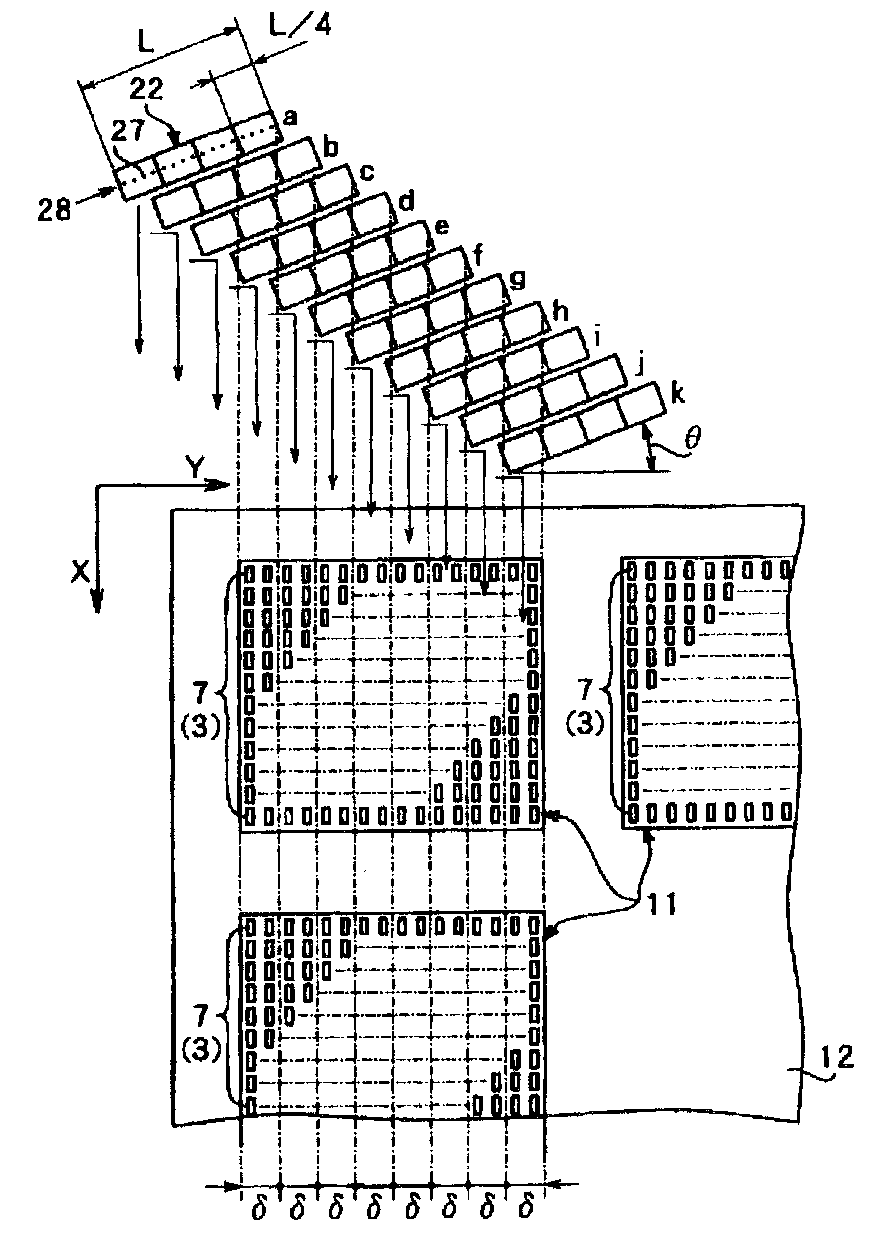
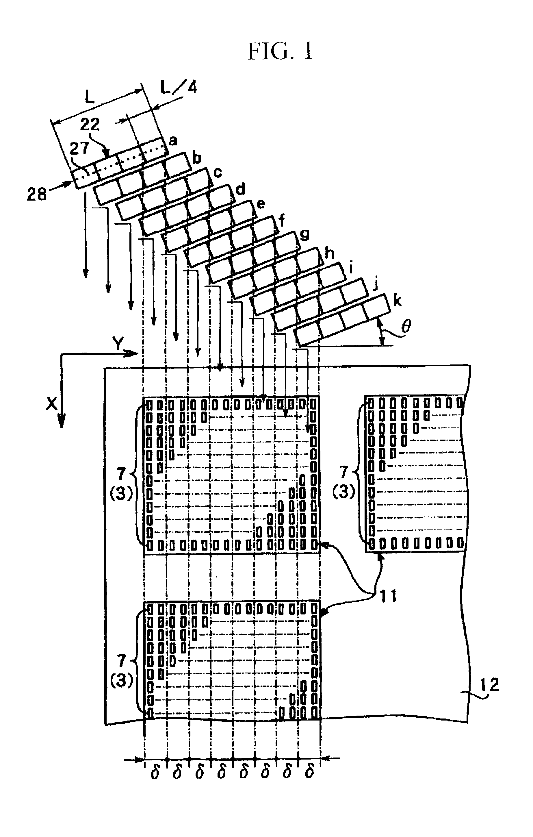
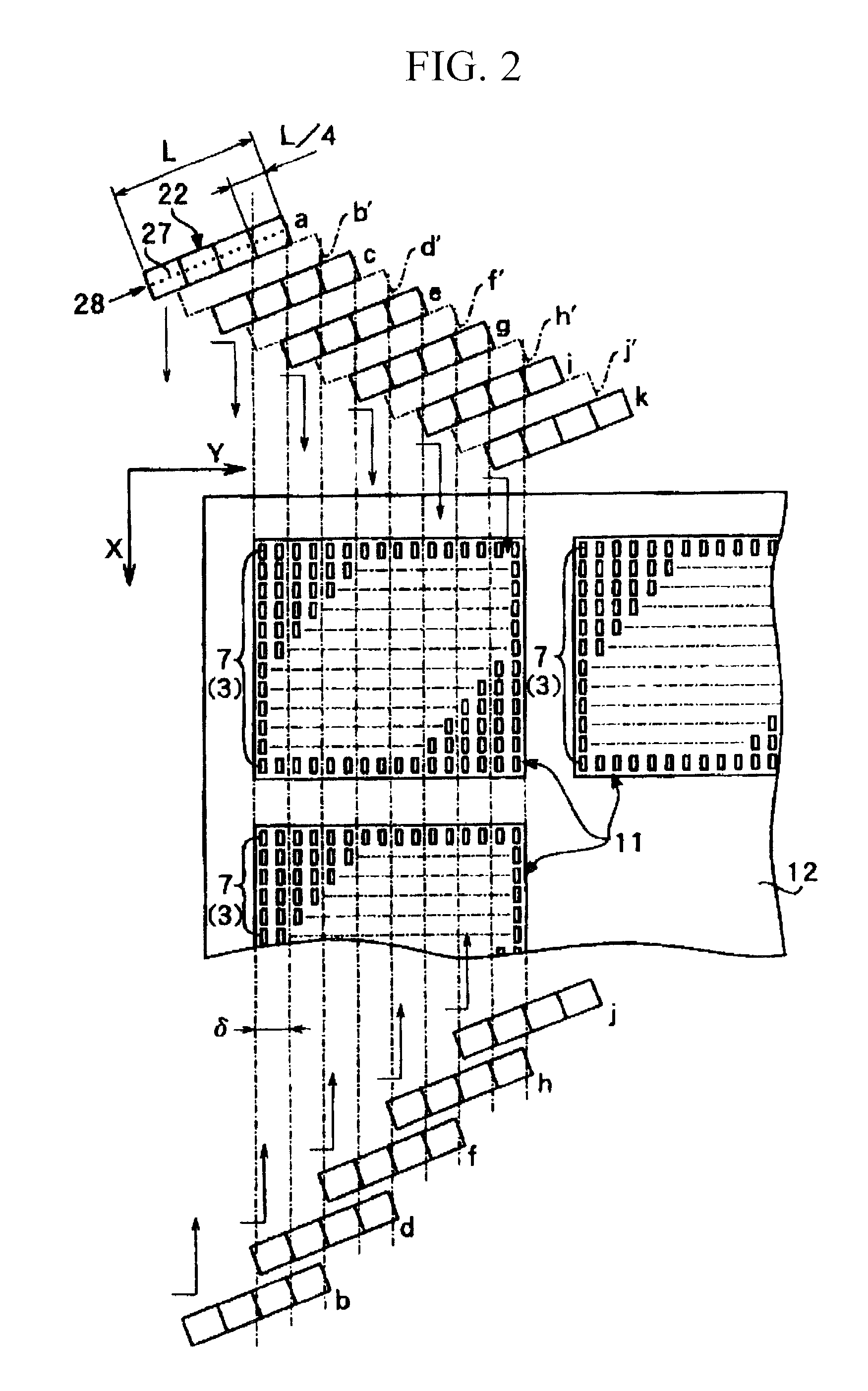
In an ink jet apparatus for manufacturing a color filter 1, ink jet heads 22 having a plurality of nozzle 27 are disposed in a linear manner. Filter element member is ejected to a motherboard 12 from a plurality of nozzles 27 four times so as to form the filter element 3 in a predetermined thickness. By doing this, it is possible to prevent difference in the thickness in a plurality of the filter elements 3 and to equalize light transparency in planar manner. Thus, in an ejecting apparatus, a color filter can be formed in more common way at low cost and more efficiently. Also, it is possible to provide an ejecting apparatus which can equalize factors such as electrooptic characteristics of the electrooptic members, color displaying characteristics by the liquid crystal apparatuses, and illuminating characteristics by an EL surface.

Description

BACKGROUND OF THE INVENTION[0001]1. Field of the Invention[0002]The present invention relates to an ejecting method for ejecting a fluid liquid material and relates to an apparatus therefor. Also, the present invention relates to an electrooptic apparatus such as a liquid crystal apparatus, an electroluminescent apparatus (hereinafter called an EL apparatus), an electrophoretic apparatus, and a plasma display panel apparatus (hereinafter called a PDP apparatus). Also, the present invention relates to a manufacturing method for an electron emission apparatus for manufacturing electrooptic apparatuses and relates to a manufacturing apparatus therefor. Also, the present invention relates to a color filter which is used in electrooptic apparatus, and to a manufacturing method for the color filter, and to a manufacturing apparatus therefor. Furthermore, the present invention relates to an electrooptic member, a semiconductor apparatus, an optical member, a device having a base member suc...

Claims


Application Information

Patent Timeline
Patent Type & Authority Patents(United States)
IPC IPC(8): B41J2/145B41J2/15B41J29/38B41J2/01B41J2/045B41J2/055B41J29/00G02B5/20G02F1/1335H01L51/50H05B33/10
CPCH05B33/10B41J29/00
Inventor NAKAMURA, SHINICHIYAMADA, YOSHIAKI
Owner KATEEVA
Learn More