
LED light source module for flashlights

a technology of led flashlights and light source modules, which is applied in the direction of semiconductor devices, lighting and heating apparatus, and light source support devices. it can solve the problem that led flashlights typically demonstrate lower beam intensity than conventional incandescent flashlights

Active Publication Date: 2006-02-21
SIGNIFY HLDG BV
View PDF19 Cites 129 Cited by
  • Summary
  • Abstract
  • Description
  • Claims
  • Application Information

AI Technical Summary

Benefits of technology

The invention is a module for an LED flashlight that includes a power source, an LED light source, a heat sink, and a reflector. The module is designed to be attached to a conventional flashlight and is operational with a flexible circuit for electrical coupling. The module provides a custom distribution pattern of energy from the LED light source. The invention also includes a circuit for controlling the current to the LED light source and a single switch for powering on / off the device. The technical effects of the invention include improved energy distribution, custom lighting patterns, and improved control over the LED light source.

Problems solved by technology

However, LED flashlights have typically demonstrated lower beam intensity than conventional incandescent flashlights.

Method used


Image

  • LED light source module for flashlights
  • LED light source module for flashlights
  • LED light source module for flashlights

Examples


Embodiment Construction

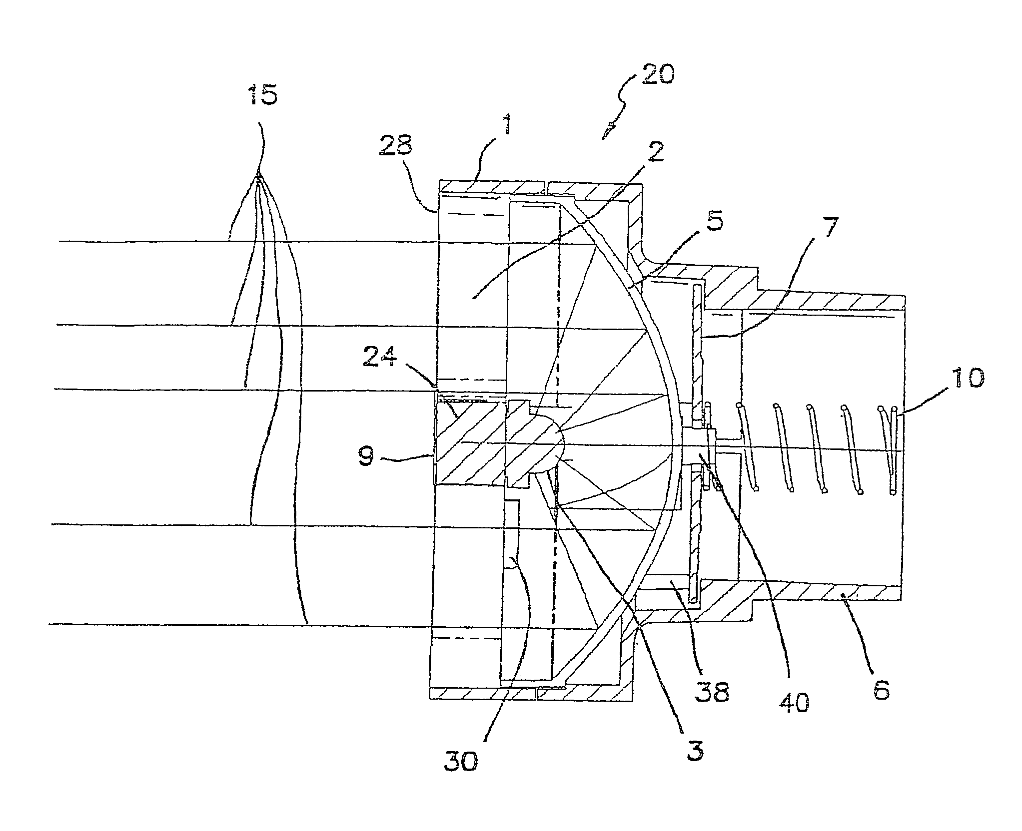
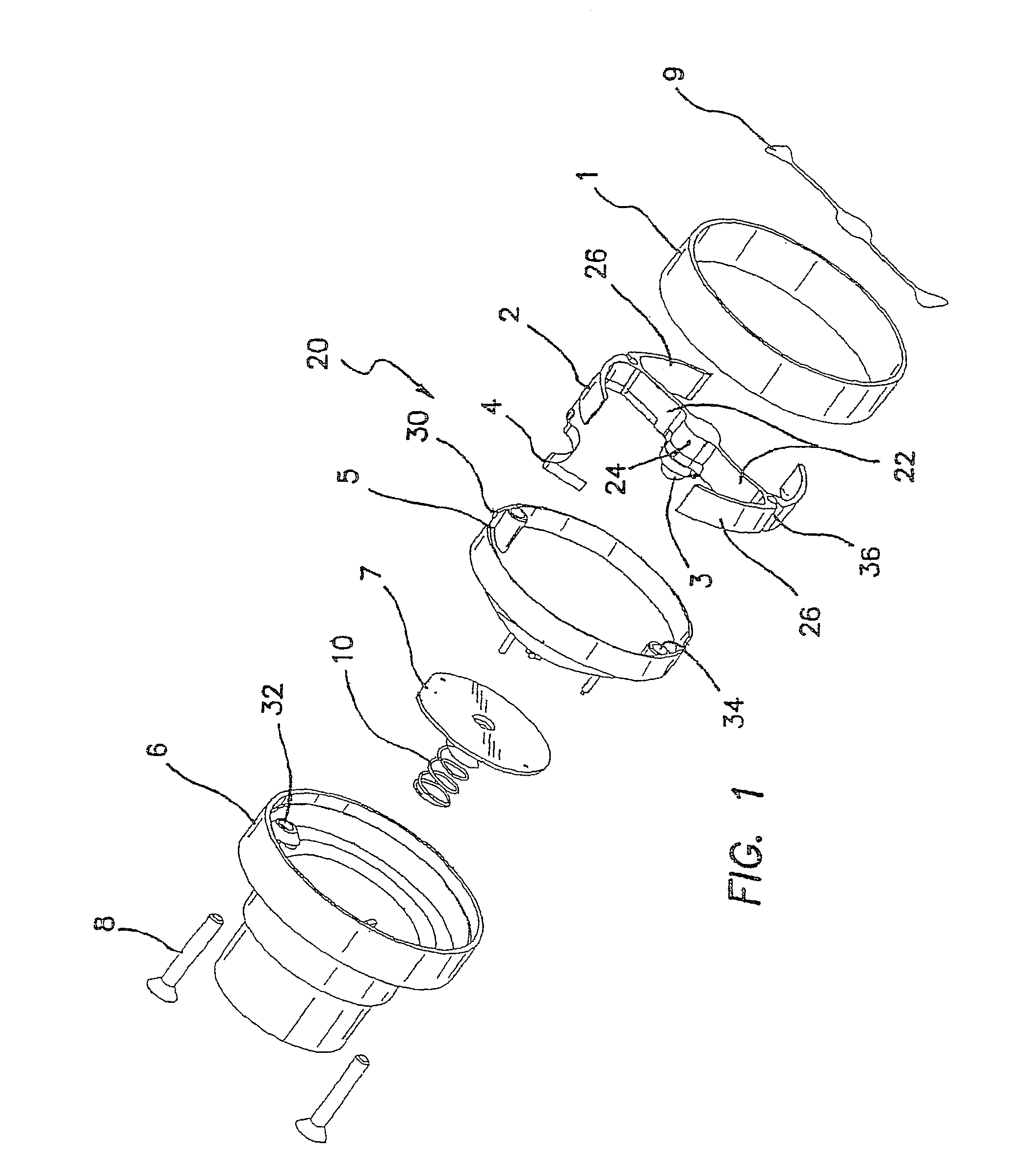
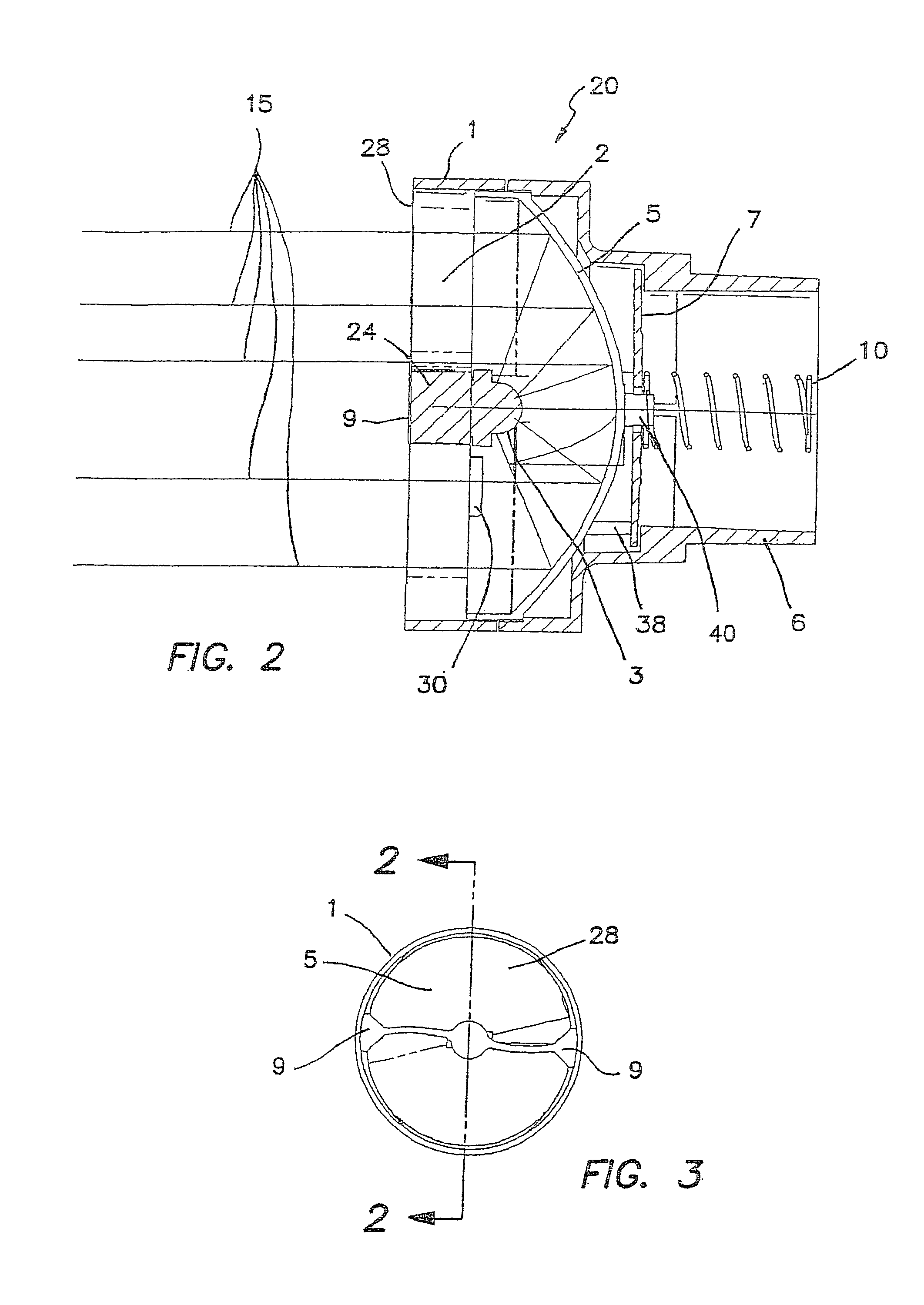
[0022]The invention pertains to the use of light emitting diodes (LED) in a flashlight, which will typically include a flashlight body 12 (shown in FIG. 4), a power source, controls or switches and an illumination module 20, or components disposed and arranged in the flashlight body 12 similarly to their respective positions in the shown module. In the following disclosure for the sake of simplicity, only the illumination module 20, or its equivalent discreet components, will be described, but it must be understood that the scope of the invention includes all the elements of a conventional flashlight, including but not limited to a flashlight body 12, a power source, controls or switches, which will not be further described. The invention provides for the efficient collection and distribution of light emanating from an LED 3 or an array of LEDs 3. The invention further includes thermal management and may include electronic control of the LED(S) 3.

[0023]A preferred embodiment of the ...


PUM


Abstract

A module, or collection of discreet components, for an LED flashlight is coupled to a conventional flashlight body which includes a conventional power source. The module comprise a housing adapted to be coupled to the flashlight body; an LED light source coupled to the power source; a heat sink coupled to the housing, which heat sink is thermally and mechanically coupled to the LED light source; and a reflector coupled to the housing and having an optical axis. The LED light source is positioned by the heat sink on or near the optical axis and is optically coupled to the reflector. The reflector reflects light from the LED light source in a forward direction. The module, and / or components, is arranged and configured to be operatively coupled as a unit to the flashlight body and power source.

Description

RELATED APPLICATIONS[0001]The present application is related to U.S. Provisional Patent Application, Ser. No. 60 / 477,319, filed on Jun. 10, 2003, which is incorporated herein by reference and to which priority is claimed pursuant to 35 USC 119.BACKGROUND OF THE INVENTION[0002]1. Field of the Invention[0003]The invention relates to the field of portable handheld lighting devices and in particular to LED flashlights.[0004]2. Description of the Prior Art[0005]The minimum requirements for a common flashlight are: an energy source, typically a battery or batteries, a light source, usually an incandescent lamp, or more recently an LED or an array of LEDs, a means of switching the energy on and off, and a case or housing. LED flashlights are advantageous in that they typically have longer lamp and battery lives, due in large part to their lower power consumption and lower operating temperatures as compared to incandescent units. The better designed LED flashlights have the same or a greate...

Claims


Application Information

Patent Timeline
Patent Type & Authority Patents(United States)
IPC IPC(8): F21V7/20F21L4/00F21L4/02F21V7/00F21V14/02F21V29/00F21V29/505
CPCF21L4/027F21V29/773F21V29/004F21V14/025F21L4/005F21V7/0008F21Y2101/02Y10S362/80F21Y2115/10
Inventor HOLDER, RONALD GARRISONRHOADS, GREG
Owner SIGNIFY HLDG BV
Learn More