Transmitting jack with prong-type conductive pieces

Active Publication Date: 2006-02-21
JYH ENG TECH
View PDF16 Cites 41 Cited by
  • Summary
  • Abstract
  • Description
  • Claims
  • Application Information

AI Technical Summary

Benefits of technology

[0009]The primary object of the present invention is to provide a transmitting jack with prong-type electrically conductive pieces free of an assembling tool, the structure is pivotally connected on its housing with a pair of openable/closable tailing seats—an upper and a lower tailing seat—for enveloping transmitting lines. The upper and the lower tailing seats each is provided therein with an inclined block; the two inclined blocks will move along inclined surfaces on the tailing end of a passage seat when they are closed to each other, and then are closed together; when in closing, the upper and the lower tailing seats will push a passage seat frontwardly of the housing, so that the transmitting lines in the passage seat are pierced by prongs of metallic electrically conductive pieces for connecting. By this, there is no tool required for completing assembling of the entire jack, and thereby time efficiency can be largely increased and c

Problems solved by technology

However, conventional designing for a jack structure must use some particular tools to finish piercing of metallic electrically conductive pieces through the transmitting lines, this not only increases working hours for assembling the jack, but also is not benefit to the cost of working.
Besides, a conventional structure of transmitting jack w

Method used


Image

  • Transmitting jack with prong-type conductive pieces
  • Transmitting jack with prong-type conductive pieces
  • Transmitting jack with prong-type conductive pieces

Examples


Example

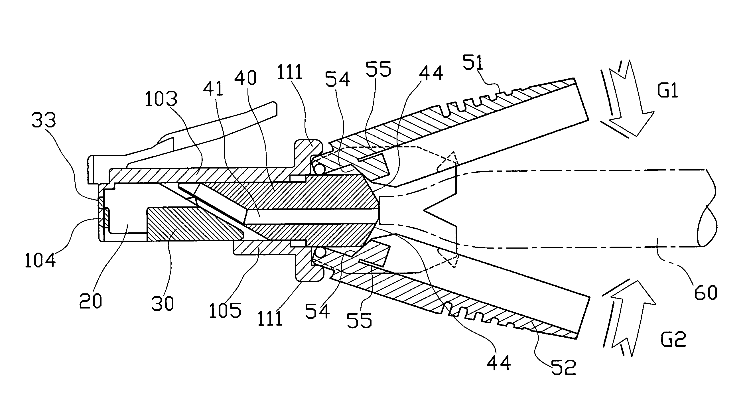
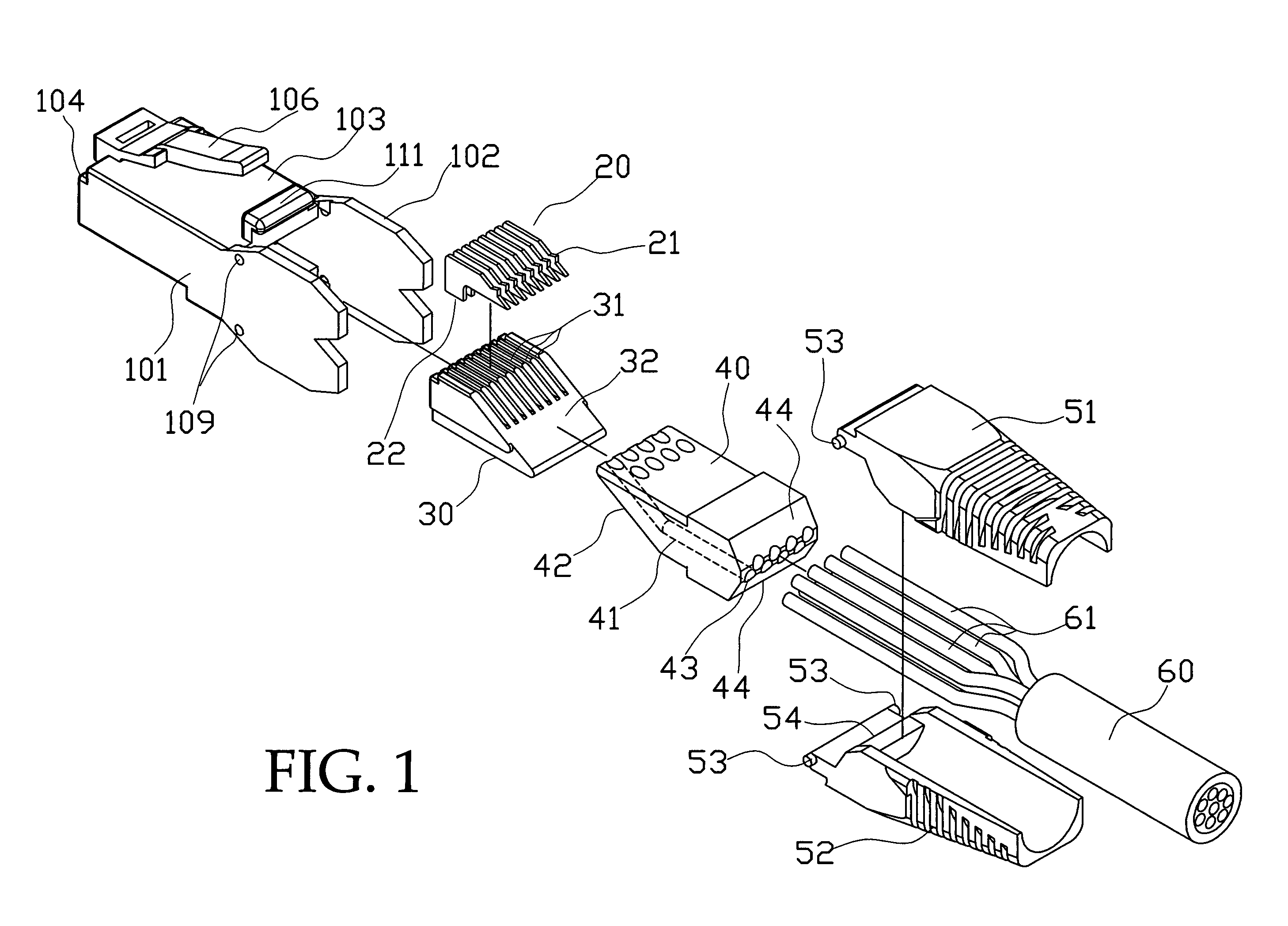
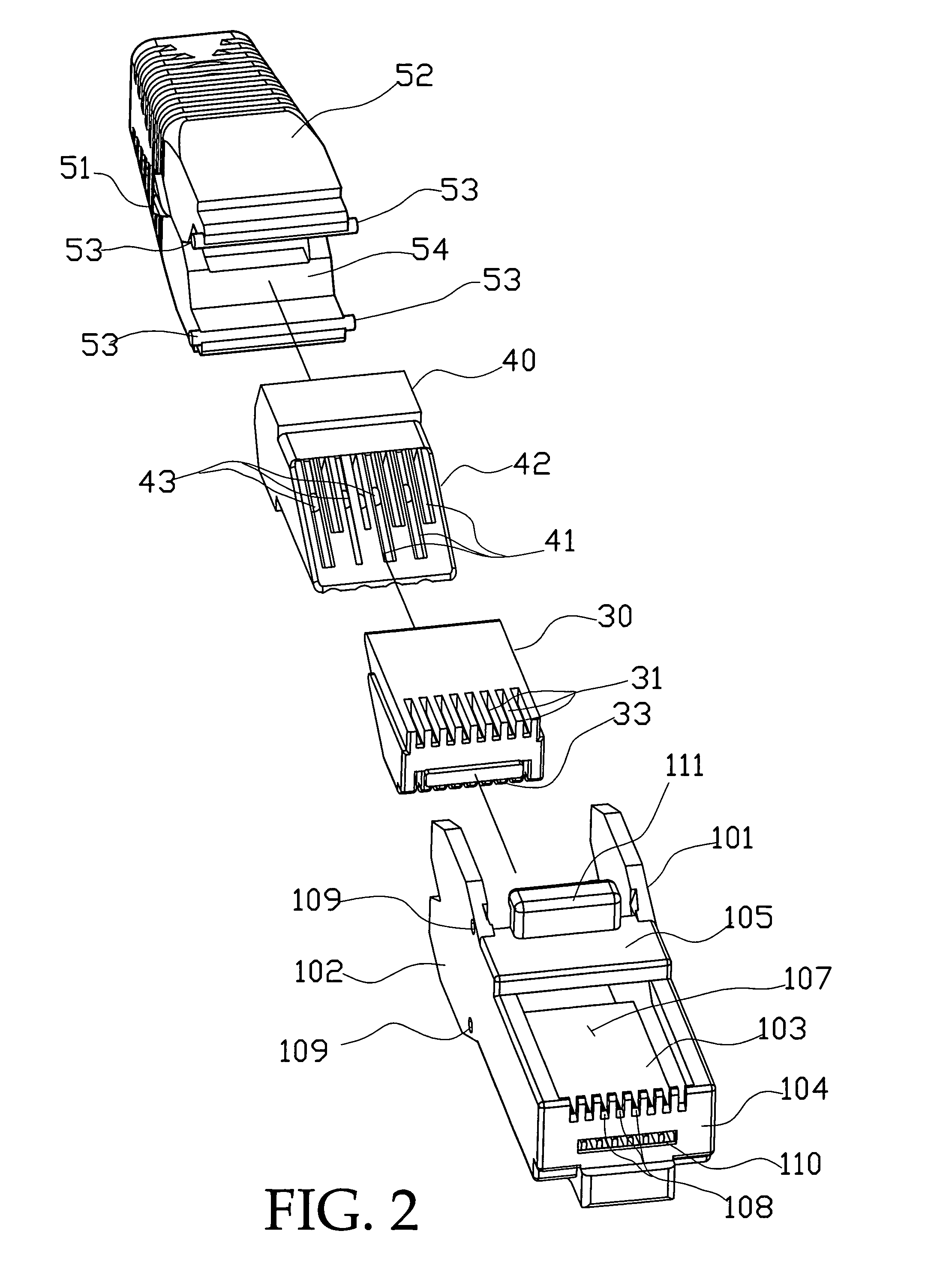
[0018]Referring to FIGS. 1–3, the present invention has an insulation housing 10; the insulation housing 10 has a front section that can be inserted into a jack hole of a communication jack, and has two lateral sides 101 and 102, a top surface 103, a front surface 104, and a bottom surface 105 (reference to FIG. 2).

[0019]There is an elastic clamping strip 106 on the top surface 103 for fixing of a plug in the jack.

[0020]The two lateral sides 101 and 102 have their top edges connected to the top surface 103, and have their bottom edges connected to the bottom surface 105. The bottom surface 105 and the front surface 104 are formed therebetween an empty area 107.

[0021]The front surface 104 is provided with an elongate hole 110, and is provided on its bottom edge with a plurality of slits 108.

[0022]The two lateral sides 101 and 102 are provided each with a round hole 109 to pivotally connect an upper and a lower tailing seat 51, 52.

[0023]The insulation housing 10 is provided therein wi...


PUM


Abstract

In the transmitting jack, a housing has a seat for mounting multiple metallic electrically conductive pieces, and has a passage seat for extending therethrough of transmitting lines in a communication line. The transmitting lines are located in slots provided on the seat for the metallic electrically conductive pieces; prongs provided on the metallic electrically conductive pieces can be extended through insulating coats on the transmitting lines for electric conduction. The housing is pivotally connected with a pair of tailing seats enveloping the communication line. The tailing seats each has therein an inclined block; the blocks move along inclined surfaces on the tailing end of the passage seat when they are closed up to each other; and the tailing seats will push the passage seat frontwardly of the housing, so that the transmitting lines in the passage seat are pierced by the prongs for connecting. By this, there is no tool required for completing assembling of the entire jack.

Description

BACKGROUND OF THE INVENTION[0001]1. Field of the Invention[0002]The present invention is related to a new structure of high-speed signal transmitting jack with prong-type electrically conductive pieces, and especially to a transmitting jack capable of being assembled without any tool.[0003]2. Description of the Prior Art[0004]Cable network transmitting available nowadays can only be completed by inputting to computers with communication cables. There are eight transmitting lines in a communication cable, in addition to these, the transmitting lines are coated with insulating coats. The communication cables must use transmitting jacks to get connecting into the computers, such as use RJ45 connectors, so that data can be input into the computers or uploaded from the computers.[0005]A conventional jack structure has passage ways in its insulation housing for extending of transmitting lines therein, then metallic electrically conductive pieces can thus be connected. Generally used metal...

Claims


Application Information

Patent Timeline
IPC IPC(8): H01R11/20
CPCH01R24/64H01R4/2433
Inventor LIN, YEN-LIN
Owner JYH ENG TECH
Why Eureka
Try Eureka