Surgical device with expandable member

a surgical device and expandable technology, applied in the field of expandable members, can solve the problems of limited jaw length, malformation of staples, and greater potential for malformation, and achieve the effect of increasing the rigidity of the end effector

a surgical device and expandable technology, applied in the field of expandable members, can solve the problems of limited jaw length, malformation of staples, and greater potential for malformation, and achieve the effect of increasing the rigidity of the end effector

US7001408B2Active Publication Date: 2006-02-21ETHICON ENDO SURGERY INC

Image

  • Surgical device with expandable member
  • Surgical device with expandable member
  • Surgical device with expandable member

Examples


Embodiment Construction

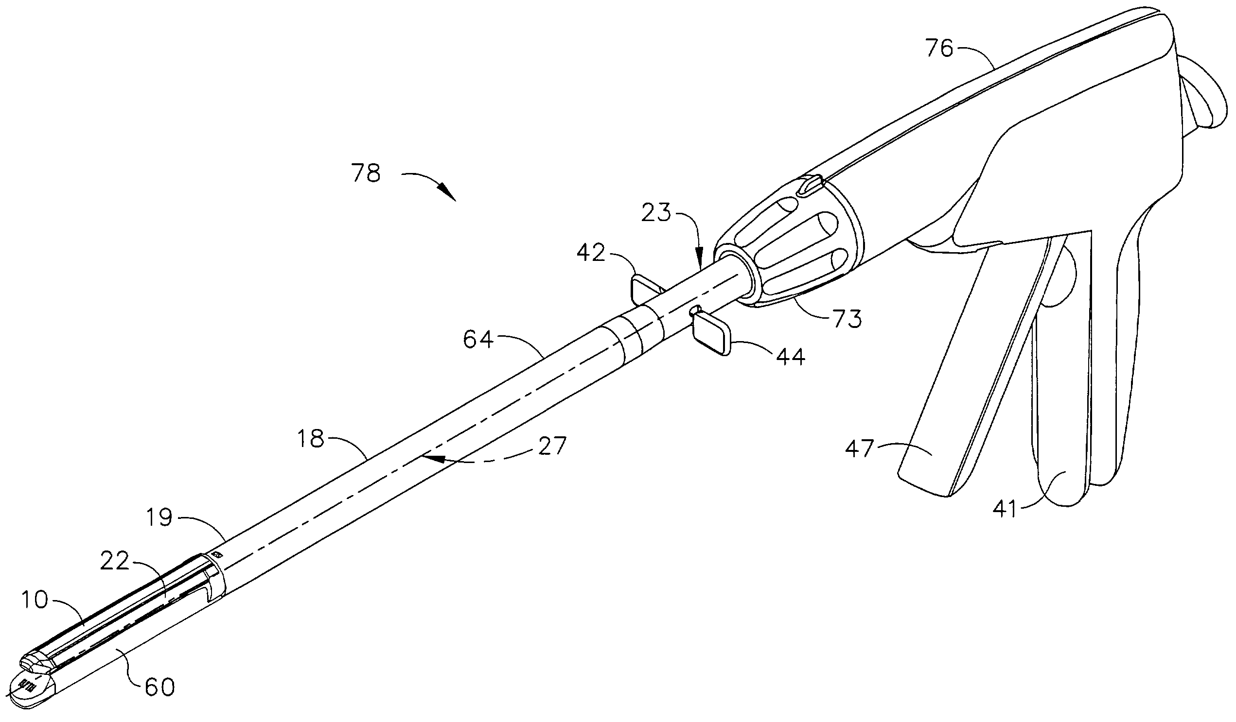
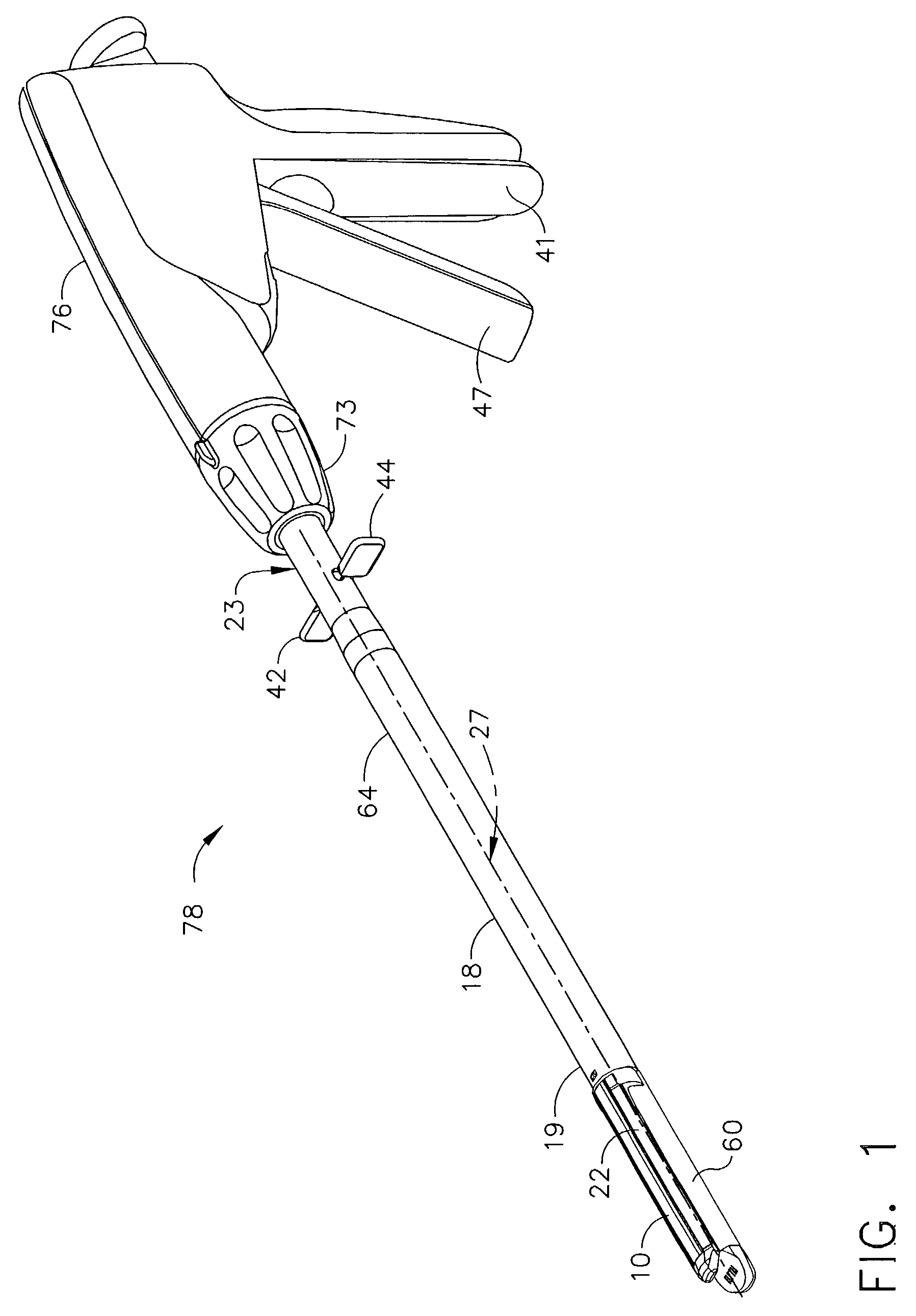
[0018]FIG. 1 shows a surgical device 78 for manipulating tissue. Surgical device 78 has a first and a second jaw, and one of the jaws is equipped with an expandable member according to an embodiment of the invention. In the embodiment shown in FIG. 1, the expandable member is an anvil cap 10. Anvil cap 10 is shown on one of the jaws, anvil 22, which is closed adjacent to a second jaw, or cartridge 60. Cartridge 60 contains staples 61 (FIG. 2), which can be ejected into tissue to be formed into shape to join and retain the tissue by pockets within anvil 22. Anvil 22 and cartridge 60 are located at a distal end 19 of an elongated shaft 18. Shaft 18 in the embodiment depicted further comprises a tube 64 extending along a longitudinal axis 27 proximally towards a rotation knob 73 and a handle 76. Handle 76 attaches at a proximal end 23 of shaft 18. Right thumbpad 42 and left thumbpad 44 extend from shaft 18, as an expander actuator, to be grasped by a physician to expand anvil 22, as wi...


PUM


Abstract

A surgical device for manipulating tissue. The device includes an elongated shaft having a proximal end and a distal end extending therefrom. There is also an elongated end effector having a proximal end attached to the distal end of the shaft, a distal end extending therefrom. The end effector has first and second opposing jaws which are movable with respect to each other from an open position, wherein the jaws are spaced apart, to a closed position wherein the jaws are in close approximation to one another. At least one of the jaws has an expandable member disposed thereon for selectively increasing the size of the jaw in a direction perpendicular to the longitudinal axis so as to increase the rigidity of the end effector.

Description

[0001]This application is related to the copending U.S. patent application Ser. No. 10 / 247,897, which is hereby incorporated herein by reference.FIELD OF THE INVENTION[0002]The present invention has application in conventional endoscopic and open surgical instrumentation as well as application in robotic or power assisted surgery. The present invention relates, in general, to an expandable member to stiffen a jaw of a surgical device and, more particularly, to an anvil cap movable to a position to increase the height of an anvil of an endoscopic linear cutter.BACKGROUND OF THE INVENTION[0003]Medical devices to simultaneously cut and staple tissue in a surgical patient, often called linear cutters, are commonly used in endoscopic surgery. In endoscopic surgery, linear cutters are placed into the patient through a cannula having a small orifice. Each linear cutter generally has an end-effector in the form of a cartridge, for holding and ejecting staples, and an anvil, for forming the ...

Claims


Application Information

Patent Timeline
21 Feb 2006
Publication
US7001408B2
IPC
A61B17/28; A61B17/00; A61B17/068; A61B17/072; A61B17/32
CPC
A61B17/07207; A61B17/0686; A61B2017/07214; A61B2017/00353; A61B17/320016
Inventors
KNODEL, BRYAN D.; KNODEL, TIMOTHY B.