Systems and methods for boundary detection in images

a technology of image boundary and detection method, applied in image enhancement, image data processing, instruments, etc., can solve the problems of inability to integrate methods with methods, methods have not been supported by simple user interfaces or compatible “edge tools”, and methods have not been well-developed for finding relatively precise positions. , to achieve the effect of accurately locating an edge position, easy integration, and convenient integration

Inactive Publication Date: 2006-02-21
MITUTOYO CORP
View PDF18 Cites 69 Cited by
  • Summary
  • Abstract
  • Description
  • Claims
  • Application Information

AI Technical Summary

Benefits of technology

[0014]Accordingly, because many operators of conventional machine vision systems desire a more standardized edge locating capability which supports increasingly robust operations with minimal user understanding and / or intervention, there is a need for systems and methods that can be used with existing machine vision systems that can precisely detect the position of a boundary, i.e., an edge, between regions using image characteristics other than intensity gradients or differentials so that images of edges that are not well-defined by changes in intensity can be more accurately detected and located.
[0016]This invention separately provides systems and methods that accurately locate an edge position bounded or defined by one or two significantly textured regions as an easily integrated supplement and / or alternative to intensity-gradient type edge locating operations.
[0017]This invention separately provides systems and methods that accurately locate an edge position bounded by one or two significantly colored regions or color-textured regions as an easily integrated supplement and / or alternative to intensity-gradient type edge locating operations.
[0024]A boundary detection tool in accordance with the systems and methods according to this invention optionally allows a user to specify the shape, the location, the orientation, the size and / or the separation of two or more pairs of sub-regions-of-interest bounding the edge to be located. Alternatively, the machine vision systems and methods according to this invention can operate automatically to determine the sub-regions-of-interest. If conventional intensity gradient-based edge-locating operations are not appropriate for locating the edge included in the primary region-of-interest, then the sub-regions-of-interest are used as training regions to determine a set of texture-based features which can be used to effectively separate the feature values of pixels on either side of the included edge into two distinct classes or clusters. A pseudo-image, such as a membership image, is calculated using the feature images. Gradient operations can then be applied to the membership image to detect the desired edge and determine its location. Post-processing can be applied to the edge data, using input data related to known features and approximate locations of the edge, to remove outliers and otherwise improve the reliability of the edge location. These and other features and advantages of the this invention allow relatively unskilled users to operate a general-purpose machine vision system in a manner that precisely and repeatably locates edges in a variety of situations where conventional intensity gradient methods locate edges unreliably or fail to locate the edges altogether.

Problems solved by technology

Accordingly, texture-based segmentation methods and image-specific texture-based segmentation methods have not been well-developed for finding relatively precise positions for edge locations at the boundaries between regions.
Furthermore, such methods have not been combined with a method that automatically streamlines them and subordinates them to other edge or boundary detection operations according to the reasonably well-behaved and predictable characteristics of particular edges found on industrial inspection objects.
Moreover, these methods have not been supported by a simple user interface or compatible “edge tools” which can be used by operators having little or no understanding of the underlying mathematical or image processing operations.
Finally, no conventional machine vision system user interface supports both the operation of conventional intensity gradient-type edge locating operations and texture-type edge-locating operations with substantially similar edge-tools and / or related GUIs, or combines both types of operations for use with a single edge tool.

Method used


Image

  • Systems and methods for boundary detection in images
  • Systems and methods for boundary detection in images
  • Systems and methods for boundary detection in images

Examples


Embodiment Construction

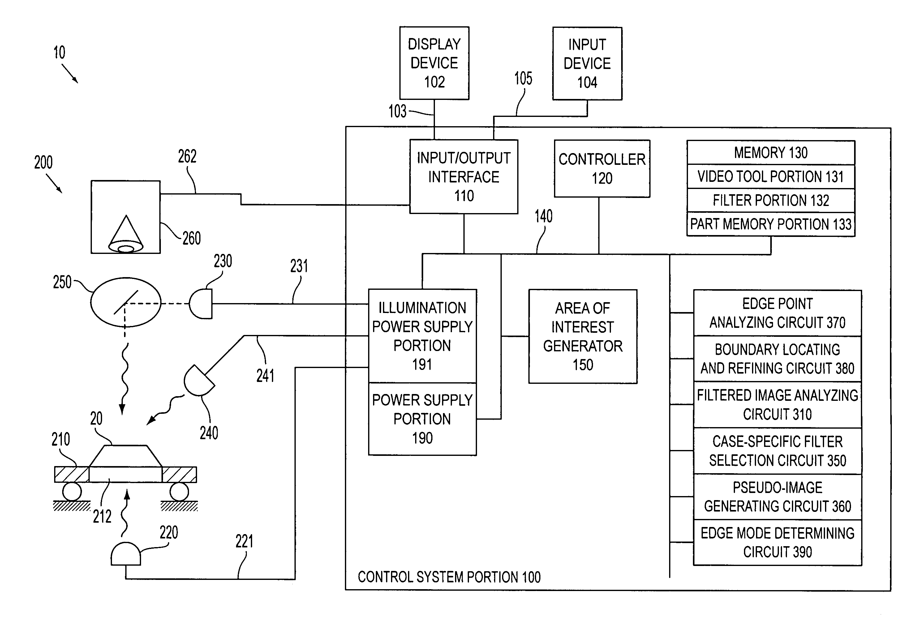
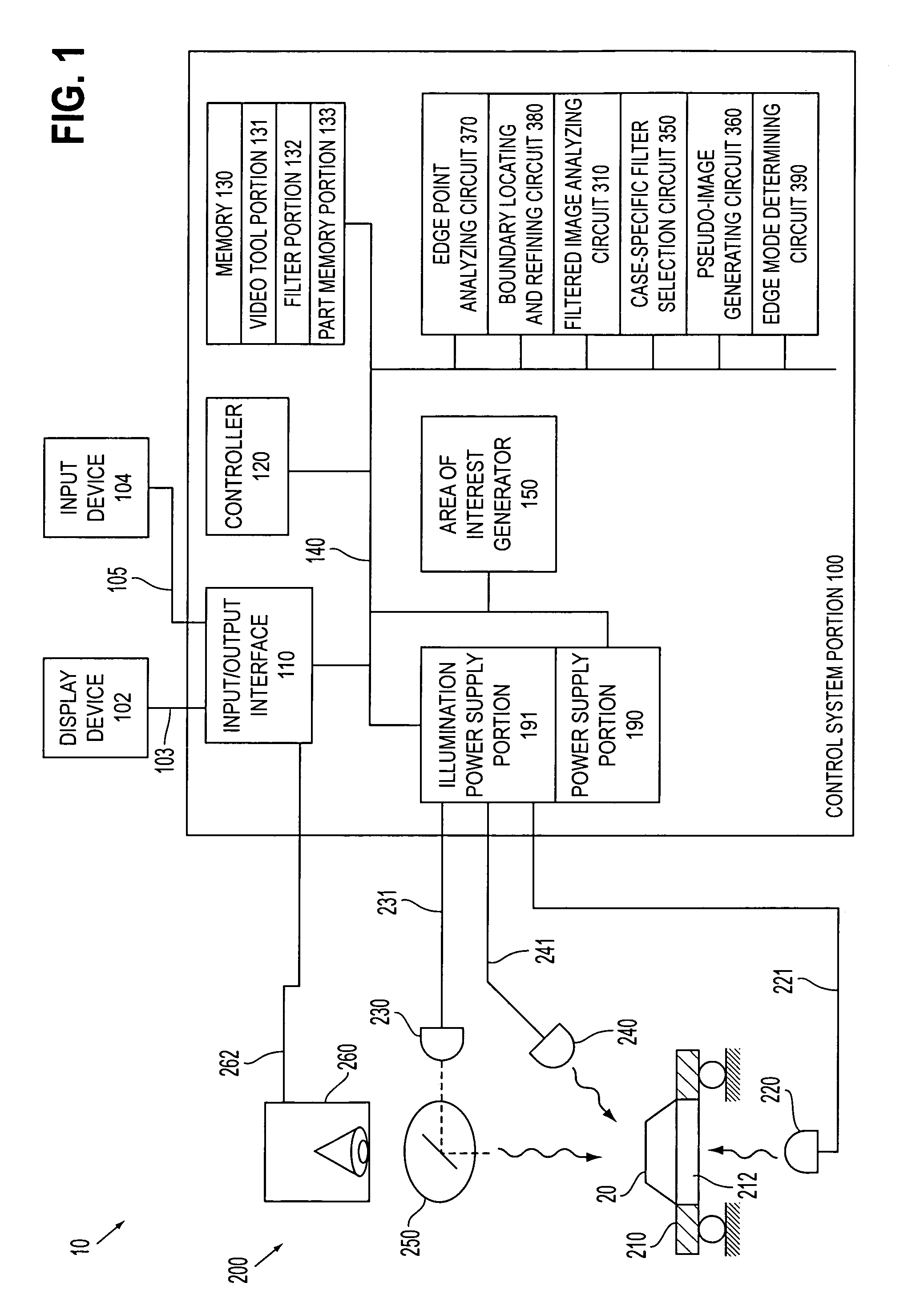
[0043]The systems and methods of this invention can be used in conjunction with the machine vision systems and / or the lighting calibration systems and methods disclosed in U.S. Pat. No. 6,239,554 B1, which is incorporated herein by reference in its entirety.

[0044]With regard to the terms “boundaries” and “edges” as used herein, the terms “boundaries” and “edges” are generally used interchangeably with respect to the scope and operations of the systems and methods of this invention. However, when the context clearly dictates, the term “edge” may further imply the edge at a discontinuity between different surface planes on an object and / or the image of that object. Similarly, the term “boundary” may further imply the boundary at a discontinuity between two textures, two colors, or two other relatively homogeneous surface properties, on a relatively planar surface of an object, and / or the image of that object.

[0045]For simplicity and clarification, the operating principles and design f...


PUM


Abstract

Systems and methods that accurately detect and locate an edge or boundary position based on a number of different characteristics of the image, such as texture, intensity, color, etc. A user can invoke a boundary detection tool to perform, for example, a texture-based edge-finding operation, possibly along with a conventional intensity gradient edge-locating operation. The boundary detection tool defines a primary region of interest that will include an edge or boundary to be located within a captured image of an object. The boundary detection tool is useable to locate edges in a current object, and to quickly and robustly locate corresponding edges of similar objects in the future.

Description

BACKGROUND OF THE INVENTION[0001]1. Field of Invention[0002]This invention relates to boundary detection and boundary location determination between two regions in images.[0003]2. Description of Related Art[0004]Many conventional machine visions systems used in locating the edges of features in images are based primarily or exclusively on applying gradient operations to the intensity values of the original image pixels. In applying gradient operations, these systems perform edge-location using the contrast inherent in the original intensity of an image. This operation is often used for machine visions systems that emphasize determining the location of edges in images of man-made work pieces with a high degree of precision and reliability. In these cases, the geometry of the edges is often well-behaved and predictable, thus providing constraints that can be applied to the edge location operations so that good results may be obtained for the majority of these images. It is also well k...

Claims


Application Information

Patent Timeline
Patent Type & Authority Patents(United States)
IPC IPC(8): G06K9/48G06T1/00G01B11/02G06T5/00G06T5/20G06T7/60
CPCG06T7/0083G06T2207/10016G06T7/12
Inventor TESSADRO, ANA M.
Owner MITUTOYO CORP
Why Eureka
Try Eureka