
Bed with anti-rattle mechanism for a bed rail

a bed rail and anti-rattle technology, applied in the field of beds, can solve the problems of rattling of the rail in the guardrail position, noise generated, and noise, and achieve the effect of reducing the rattling of the rail

Inactive Publication Date: 2006-02-28
CARROLL HEALTHCARE
View PDF23 Cites 8 Cited by
  • Summary
  • Abstract
  • Description
  • Claims
  • Application Information

AI Technical Summary

Benefits of technology

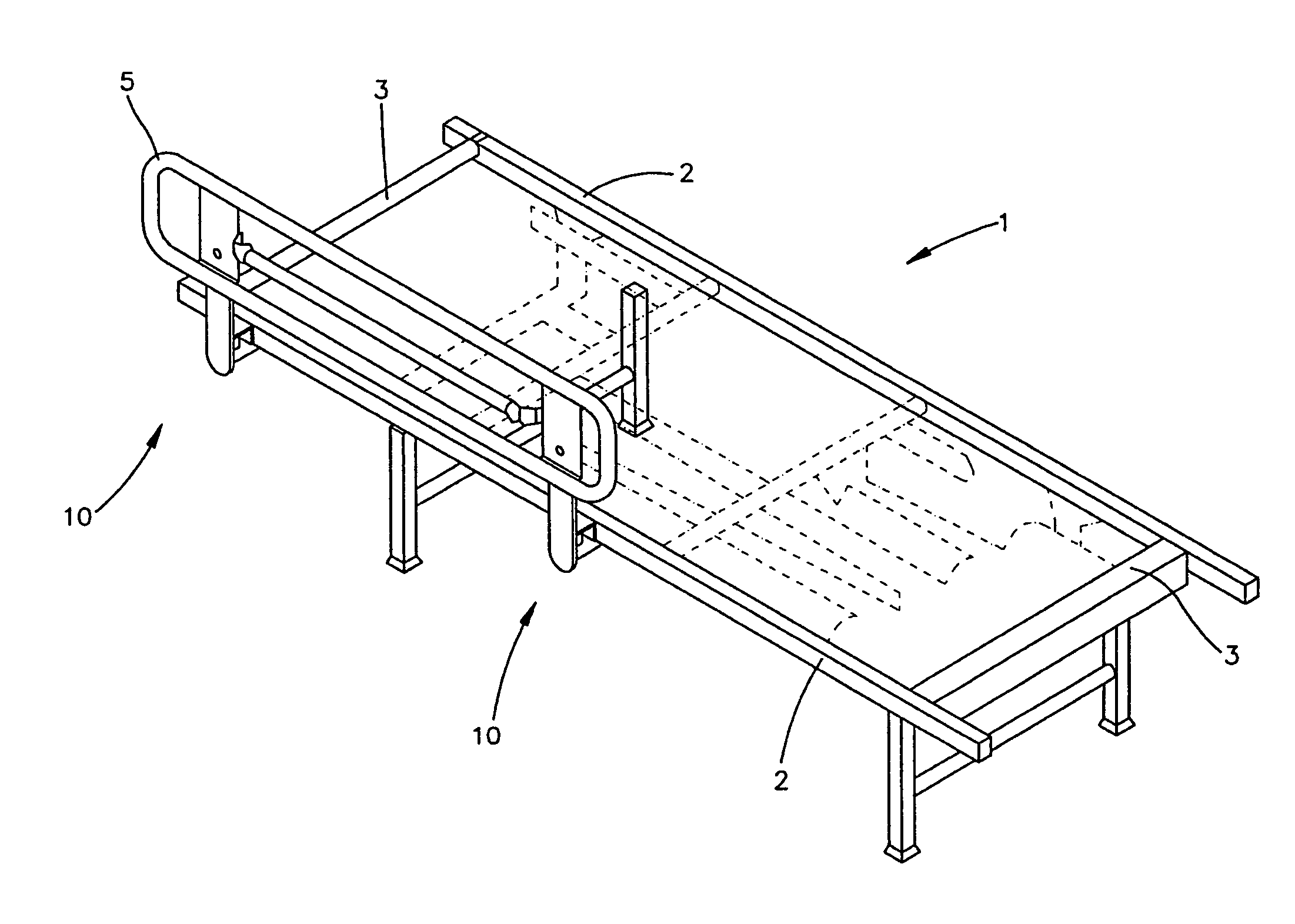
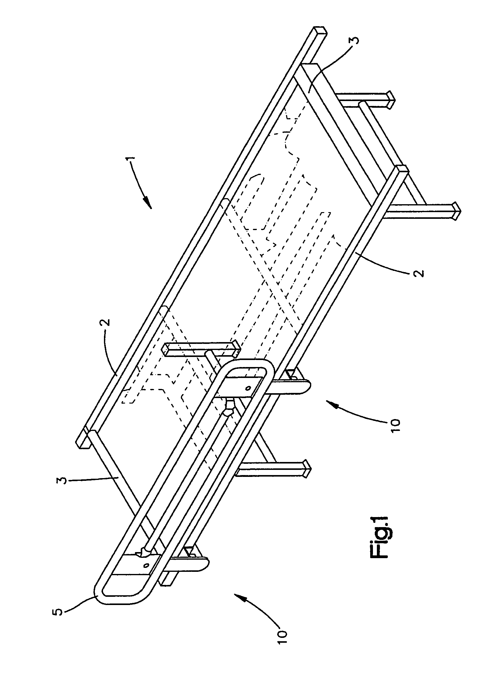
[0009]According to an aspect of the invention, there is provided a bed comprising a frame, a rail pivotally mounted on the frame and pivotable between a guardrail position and an open position, a distance between the frame and the rail when the rail is in the guardrail position, and a resilient element mounted on the frame or on the rail or on both the frame and the rail to fill the distance between the frame and the rail when the rail is in the guardrail position to thereby reduce rattling of the rail when the rail is in the guardrail position.
[0013]A resilient element may be mounted on the frame or the rail, or, both the frame and the rail may have resilient elements mounted thereon. When the rail is in the guardrail position, the resilient element or elements fill the distance between the frame and the rail. The resilient element reduces rattling of the rail when the rail is in the guardrail position. The resilient element should be mounted on the frame (or the rail) in a location where the resilient element will engage the rail (or the frame) when the rail is moved to the guardrail position. For rails which are pivotally mounted on the frame at more than one point, there may be a resilient element located near or at each pivot point to fill the distance between the frame and the rail.
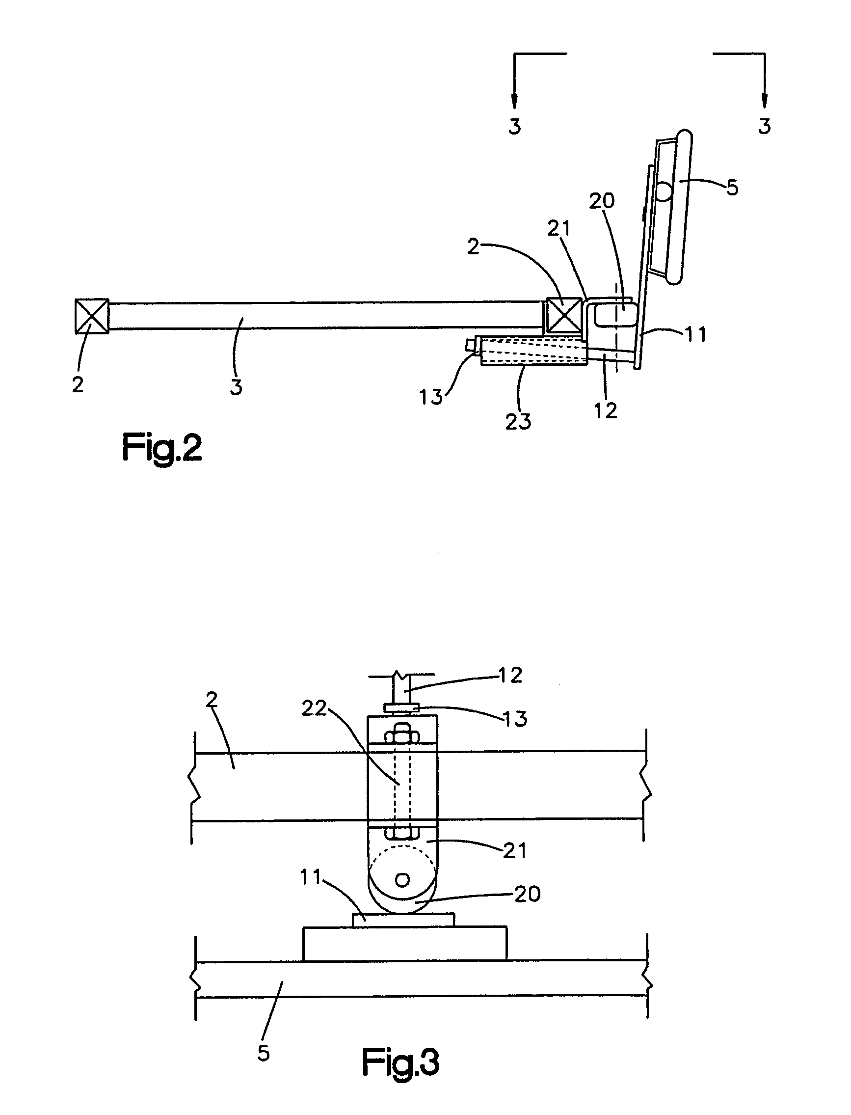
[0014]The resilient element may be made of any suitable resilient material, for example, natural or synthetic rubbers, elastomers, thermoplastic polymers, or combinations thereof. The resilient material is preferably deformable under pressure but will retain its original shape after the pressure is relieved. In this way, the resilient element can be designed to be somewhat larger than the distance between the frame and the rail but is sufficiently deformable to be forced to fit into the distance. The resilient element can then exert force on the rail and the frame due to its resiliency, to thereby help wedge the rail in position. This helps reduce rattling and helps prevent the rail from accidentally slipping out of position. One skilled in the art understands that the resilient elements may be formed of a core of non-resilient material having a resilient material affixed to a surface thereof.
[0015]In one embodiment, a resilient element is mounted on the frame. When the rail is moved from the open position to the guardrail position, the resilient element engages the rail, for example at a rail support, to fill the distance between the frame and the rail thereby wedging the rail in place to reduce rattling.
[0016]In another embodiment, a first resilient element is mounted on the frame and a second resilient element is mounted on the rail. When the rail is moved into the guardrail position the second resilient element frictionally engages the first resilient element, the two resilient elements together filling the distance between the frame and the rail. In the guardrail position, the second resilient element is compressibly held by the first resilient element to thereby reduce rattling of the rail.

Problems solved by technology

Such tolerance may lead to rattling of the rail in the guardrail position and to noise generated therefrom.
Such noise can be very annoying and intrusive, especially in a facility where the environment is intended to be as quiet as possible.

Method used


Image

  • Bed with anti-rattle mechanism for a bed rail
  • Bed with anti-rattle mechanism for a bed rail
  • Bed with anti-rattle mechanism for a bed rail

Examples


Embodiment Construction

[0026]Referring to FIGS. 1–4, a long-term care bed comprises a frame (1) having longitudinal frame elements (2) and transverse frame elements (3). A side rail (5) is pivotally mounted on one of the longitudinal frame elements (2). Another side rail may be likewise mounted on the other longitudinal frame element. The side rail (5) has two rail support structures (10), each rail support structure comprising a rail leg (11) and a rail arm (12). The rail arm (12) is journaled in an arm holder (23) mounted to the longitudinal frame element (2) by a mounting bracket (21). The rail arm (12) is equipped with a collar (13) to prevent the rail arm (12) from slipping out of the arm holder (23). The mounting bracket (21) has a generally U-shaped portion that fits on the longitudinal frame element (2) and is held in place by a bolt (22) through the longitudinal frame element (2). Mounted on the mounting bracket (21) is a resilient roller (20) which can rotate in a plane parallel to the plane of ...


PUM


Abstract

There is described a bed comprising a frame, a rail pivotally mounted on the frame and pivotable between a guardrail position and an open position, a distance between the frame and the rail when the rail is in the guardrail position, and a resilient element mounted on the frame or on the rail or on both the frame and the rail to fill the distance between the frame and the rail when the rail is in the guardrail position to thereby reduce rattling of the rail when the rail is in the guardrail position. The resilient element is preferably a resilient roller mounted on the frame, the roller engaging the rail when the rail is pivoted into the guardrail position.

Description

FIELD OF THE INVENTION[0001]The present invention relates to beds, in particular hospital and long-term care beds, having rails and to anti-rattle mechanisms for bed rails.BACKGROUND OF THE INVENTION[0002]A bed rail on a bed, for example a hospital or long-term care bed, is used in a so-called guardrail position (also called a closed position) to keep a person from falling out of the bed and then moved to an open position to allow the person to exit the bed. As such, the bed rail must be moved, for example rotated, from the guardrail position to the open position, or vice versa. In order to move the rail efficiently, it is usually necessary to design tolerance between the moving parts and other parts on the bed. Such tolerance may lead to rattling of the rail in the guardrail position and to noise generated therefrom. Such noise can be very annoying and intrusive, especially in a facility where the environment is intended to be as quiet as possible. Therefore, there is a need in the...

Claims


Application Information

Patent Timeline
Patent Type & Authority Patents(United States)
IPC IPC(8): A47C21/08
CPCA47C21/08A61G7/0507A61G2007/0509A61G7/0509
Inventor ROUSSY, GEORGE JOSEPH
Owner CARROLL HEALTHCARE
Learn More